DIALux interface
If you use DIALux for lighting design, you can transfer the rooms from DDS-CAD. In DIALux you do the lighting plan and import it to DDS-CAD again.
Required conditions
The rooms are defined with the functions of the building model.
Workflow
 Start the function
|
|
Light Calculation (DIALux) |
-
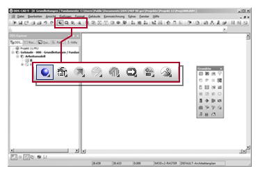
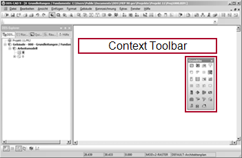
Activate:Default Tools

-
Select the function inContext Toolbar
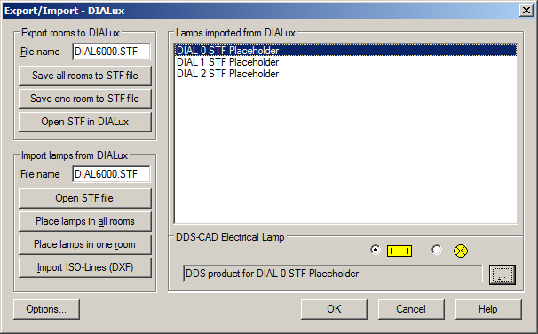
The dialog appears: Export/Import - DIALux
 Transfer rooms to DIAlux and start calculation
-
You can export all rooms of the storey or a single room.
ClickSave all rooms to STF file. The export file is created. You can start the calculation program.
- ClickSave one room to STF file
The cursor appears as a crosshair. - Click
 in the desired room.The export file is created. You can start the calculation program.
- ClickSave one room to STF file
- ClickOpen STF in DIALux
DIALux starts and opens all the exported rooms. - Do the lighting design and save the results in DIALux.
 Take luminaries from DIALux
DIALux has exported information about the description and position of the luminaries in the export file. DDS-CAD needs to import the file again.
ClickOpen STF file.
DDS-CAD reads the changed transfer file.  Lamps imported from DIALux lists the luminaries used.
 Map luminaries from DIALux with DDS-CAD objects
You need to map each of the luminary types to an object from the DDS-CAD product database.
- At Lamps imported from DIALux you select an entry by clicking .
-
Select the
function, with which luminary it should be mapped in DDS-CAD.
Lamps (various) 
Fluorescent Lamp - Click ... . The product database appears.
-
Map a product to the luminary. For each lamp type from DIALux you should create a corresponding
product in DDS-CAD.
The object dialog of a luminary appears.- Click ... . The product database appears.
- Switch to the filter to which a new product should be created.
- Select a suitable product as a template. A product is suitable as a template if it matches in as many properties with the new product.
- Click
 . The context menu appears.
 - Select:Copy
The template is copied. The product number is automatically generated and the description begins with the word copy. You can edit the copied product and customize its properties.
- Select the copy by clicking . The context menu appears.
- Select:Change
The dialog appears: Change Product - Edit the data fields of the new product and click OK. The dialog is closed. You return to the main dialog of the product database. You can use the product in the current project.
Alphanumeric character string (maximum of 15 characters) for the unique identification of the object in the parts list. DDS‑CAD automatically suggests a character string when a new product is created. You can accept the suggestion or replace it with a number. DDS‑CAD prevents duplicate numbers automatically.
Character string (max. 256 characters) for a verbal description of the product. The text appears as a selection aid in the product database and in evaluations (parts lists, calculation reports).
Code to call a symbol that was created with DDS-CAD and corresponds to the file name of a specified convention. The input is irrelevant when
 External symbol refers to a different symbol.
Combined parameter for defining the electrical power of a luminaire and its number of tubes per luminaire. With an electrical connection to the distribution board (with a cable), DDS-CAD retrieves the resulting power of the tubes and as a result calculates the operating current of the circuit.
Example
The luminaire has two tubes, each 58W.
Syntax
58.2
Function Code Effect No specification 0 All settings are made in the dialog of the luminary. Roof Type Mounting 1 
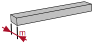
Top view
The symbol size is determined by Dimension X and Dimension Y.
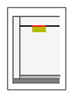
Side view
The upper edge of the object is the reference of the mounting height. The product property Dimension Z determines the depth.
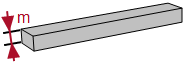
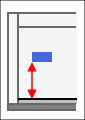
Flush Type Mounting 2
Top view
The symbol size is determined by Dimension X and Dimension Y.
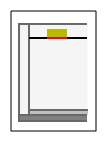
Side view
The lower edge of the object is the reference for the mounting height. The product property Dimension Z determines the depth.
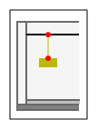
Pendant Type Mounting 3
Top view
The symbol size is determined by Dimension X and Dimension Y.
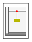
Side view
The upper point of the pendulum is the reference of the mounting height. The product property Dimension Z determines the depth.
Wall Type Mounting 9 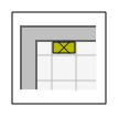
Top view
The symbol is rotated by 90° in its X-axis. The symbol size is determined by Dimension X and Dimension Z.
Side view
The central axis of the object is the reference for the mounting height. The product property Dimension X and Dimension Y determine the size.
Individual luminous flux of the luminary in lumens (lm). The default value is defined by the function Light Calculation (Efficiency Method).
Material code for representation in the rendered model.
Field for an individual text block of the part text with up to a maximum of eight characters in length.
Example
Suppose you use various luminaries in the project. The product differ in technical details, but have the same representation. In this case, you can highlight the differences by an additional marking. Enter a code in
Product text II (8 signs) and activate this text block in the part text function. If necessary, you can explain the meaning of the signs in an additional document.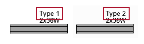 GTIN / EAN (not used)
Numeric code fur using a pen for the representation in the model.
Setting Effect 0 The object is displayed with the default pen of its object type. ≠0 The object is not displayed with the default pen of its object type. The number corresponds to the ID of the pen in the dialog Pen table.
- Close all dialogs.
- Select:Format
 Project's Pen, Layer, Font Setups
The dialog appears: Project Properties. - Activate:
 Pen
Pen - ClickEdit....
The dialog appears: Pen table. - Search for the appropriate pen.
- To display the ID: perform a double click
 on the name of the pen. A message indicates the ID.
Numeric code for the assignment of the object to a layer.
Setting Effect 0 The object is assigned to the default layer of its object types. ≠0 The object is assigned to the inserted layer number that is available in its discipline. You can use existing or non-existing layer numbers. If you used a non-existing layer number, the layer will be automatically created by using the object in the project.
- Close all dialogs.
- Select:Format Layers...
The dialog appears: . - Deactivate:
 Display only those in use
The list shows all available layers regardless of whether they were used in the model or not. - Enter the value in
 Number.
Text string for the name of the manufacturer.
You can assign a recognition code to the object by using the function Interface for Export. For some object types, a code is already assigned. If necessary, an adjustment can be made.
Function Code General electrical utilization equipment #ZAV General electrical appliance #ZAE Room heating, general #ZAR FDS fire detector center #BMZ Elektric heating #ZEH Dishwasher #GSM Incandescent lamp #ZGL Lamp with switched socket #GLS Electric cooker #ZKH Hot water unit #HWG Motor, single phase #M1P Motor, 3 phases #M3P SDS central #RWA BS security center #AEZ Luminaire with 1 fluorescent lamp #L1L Luminaire with 2 fluorescent lamps #L2L Luminaire with 3 fluorescent lamps #L3L Luminaire with 4 fluorescent lamps #L4L Fan #FAN Washing machine #WMS Socket #AVS CEE socket #AVD Dongle code (not used)Link to an external document that is associated with this product, such as a PDF file, an Excel spreadsheet or text document. If a product contains a link you can open the document in the model. The application possibilities are endless.
- Data sheets with technical specifications of the object
- Bill of materials for composite objects
- Images
General principle:
- Start with a semicolon ;
- Enter the full path to the document.
- Spaces in the patch must be replaced with %20
Example 1: For a document in the file system
Assuming the document is on the local hard drive or a network drive.
Path in the file system C:/documents/armature devices/Pump.pdf External info
;file:///C:/documents/armature%20devices/Pump.pdf Examples 2: Document on the internet
External info
;http://www.beispiel.de/downloads/Pump.pdf If you have assigned a document to the object, you can access it within the model:
- Select the object by clicking .
- Click . The context menu appears.
- Select:Show product sheet...
The document opens within DDS-CAD in a separate window.
Reference to drawing files that need to appear instead of the once addressed in
Symbol number. The referenced files must be stored either in the Project folder or in the USER folder.You can use the following file types:
You can create the object using the geometric functions of DDS-CAD. For use as a symbol in 2D and/or 3D enter at
External symbol:Application Syntax Only 2D
(in 3D the code applies in Symbol number)name2D In 2D and 3D. name2D;name3D Only 3D
(in 2D the code applies in Symbol number);name3D You can isolate the symbol from a DWG/DXF file and save it as a CFI file. For use as a symbol in 2D and/or 3D enter at
External symbol:Application Syntax Only 2D
(in 3D the code applies in Symbol number)name2D.cfi 2D and 3D name2D.cfi;name3D.cfi Only 3D
(in 2D the code applies in Symbol number);name3D.cfi Many providers offer elaborate objects, such as boilers, sanitary objects, lighting, furnishing and decorative elements in the format *.3ds.
Important!
Please note that this could concern objects that can only be acquired by paying a fee. Copyright aspects must always be respected.
For use as a symbol in 2D and/or 3D enter at
External symbol:Application Syntax Only 2D
(in 3D the code applies in Symbol number)name2D.3ds 2D and 3D name2D.3ds;name3D.3ds Only 3D
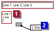
(in 2D the code applies in Symbol number);name3D.3ds Fields for free text with a maximum of three lines
 . The character ";" defines a line break.
This label is connected to the product independent from the part text
 .
.
Length of the object in meters (m). The setting only applies when using a symbol with variable size.
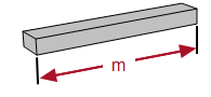
Width of the object in meters (m). The setting only applies when using a symbol with variable size.
Height of the object in meter (m). The setting only applies when using a symbol with variable size.
-
Check the settings.
This field is enabled for input if the selected product is from Mounting type 3 (Pendant Lights).
The pendant length is the distance between the point of installation
Distance and the upper edge of the suspended light.Example for mounting on Ceiling (FCL) Suspended Ceiling 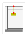
Selection of a reference line in the building to define the mounting height. The selected product determines the reference to the object.
For this function, there are products for surface mounting (on the ceiling) and flush mounting (in the ceiling).
Setting Effect Roof Type Mounting Flush Type Mounting Ceiling (FCL) 
The value at
Distance refers to the height of the ceiling (at room height).Suspended Ceiling 
The value at
Distance refers to the height of the suspended ceiling.Finished Floor (FFL) 
The value at
Distance refers to the upper edge of the Slab (SSL) 
The value at
Distance refers to the upper edge of the Free 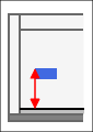
The mounting height is independent of the building model. The value in
Distance refers to the height Z=0 in the absolute coordinate system.User 1 -…User 4 -
The entries User 1 - to User 4 - contain variable standard heights. You can select and modify a standard height (e.g. User 3 -0.850). To do so,
Placement is activated for input. The entered value is stored for this entry as new standard height and can also be selected for other objects. This change has no effect on the mounting height of already inserted objects, these are automatically assigned the setting Free.Distance between the selected reference and the centre axis of the object.
In the case of settings
 Free and User 1 -… User 4 - you can enter the mounting height as a number with the desired
 The setting determines the representation of the object in the render mode when Raytracing Advance is activated
Setting Effect 
The luminary acts as a light source in the rendered model. This affects the calculation of light/shadow and reflection. The rendering is more complex and takes longer.
The luminary is not considered as a light source in the rendered model. The setting determines the appearance of the symbol in the 2D view (top view).
Setting Effect


The setting determines the location of the insertion point in the symbol. A subsequent change in this setting of an existing object causes a change in the position of the object in the model.
Setting Effect Side 
Center 
The selection is enabled when Mounting type = Wall Type Mounting. The setting defines the position of the luminary on the wall.
Setting Effect Horizontal 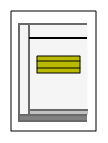
Vertical 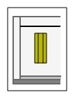
This field is enabled for input if the selected product is from Mounting type 3 (Pendant Lights).
The pendant length is the distance between the point of installation
Distance and the upper edge of the suspended light.Example for mounting on Ceiling (FCL) Suspended Ceiling
Selection of a reference line in the building to define the mounting height. The selected product determines the reference to the object.
For this function, there are products for surface mounting (on the ceiling) and flush mounting (in the ceiling).
Setting Effect Roof Type Mounting Flush Type Mounting Ceiling (FCL)
The value at
Distance refers to the height of the ceiling (at room height).Suspended Ceiling
The value at
Distance refers to the height of the suspended ceiling.Finished Floor (FFL)
The value at
Distance refers to the upper edge of the Slab (SSL)
The value at
Distance refers to the upper edge of the Free
The mounting height is independent of the building model. The value in
Distance refers to the height Z=0 in the absolute coordinate system.User 1 -…User 4 -
The entries User 1 - to User 4 - contain variable standard heights. You can select and modify a standard height (e.g. User 3 -0.850). To do so,
Placement is activated for input. The entered value is stored for this entry as new standard height and can also be selected for other objects. This change has no effect on the mounting height of already inserted objects, these are automatically assigned the setting Free.Distance between the selected reference and the centre axis of the object.
In the case of settings
Free and User 1 -… User 4 - you can enter the mounting height as a number with the desired The setting determines the representation of the object in the render mode when Raytracing Advance is activated
Setting Effect
The luminary acts as a light source in the rendered model. This affects the calculation of light/shadow and reflection. The rendering is more complex and takes longer.
The luminary is not considered as a light source in the rendered model. The setting determines the appearance of the symbol in the 2D view (top view).
Setting Effect


- Repeat the procedure for all entries.
Place lamps in all rooms and Place lamps in one room will be released once all entries are mapped to a product.
 Insert luminaries in the DDS-CAD model
You can insert all the calculated luminaries in the complete storey or step by step for each individual room.
Important!
DDS-CAD does not check whether the lights already exist in the model. If you perform this step multiple times by mistake, it will distort the parts list.
ClickPlace lamps in all rooms. All DIALux luminaries appear in the model. The operation is finished.
- ClickPlace lamps in one room
The cursor appears as a crosshair. - Click in the desired room.The luminaries of this room appear in the model.
- If you have calculated additional rooms, repeat the previous step for these rooms.