System diagram
|
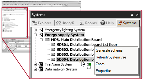
You can use DDS‑CAD to create an automatic diagram for different systems if the model fulfils the prerequisites for this. In this case, an entry appears for the respective structure in the Systems window. Click |
|||||||
|
 on an entry to open the context menu with further functions.
Prerequisites for a system diagram
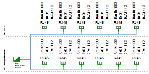
Working with the system diagram
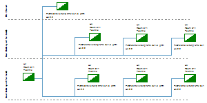
For a system diagram, DDS‑CAD evaluates the installation of the selected structure in the models of the project and generates a separate document. After making changes to the installation, you can generate a new diagram or overwrite the existing one.
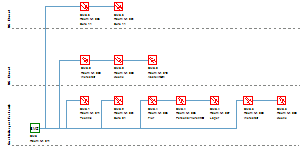
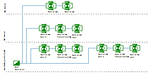
You can edit and add to the system diagram. You can control the position, visibility and labelling of the automatically adopted components and cable connections. For objects added later, you can use all other editing functions.
- Update Generate schema / diagram
- Edit automatically adopted components
- Edit automatically adopted connection lines