Construct a pipe network
General procedure
We describe possible strategies to build and develop a network in a step-wise fashion in a building with several storeys. You can deploy these operations for pipe networks with various media.
To make the job effective, consider the space requirements of the system from the beginning. Work with the expected dimensions, and think about insulation as well as possible size changes using a network calculation.
 More
MorePrepare and transfer risers.
|
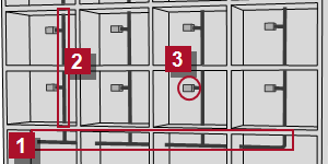
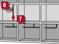
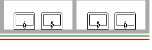
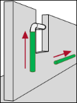
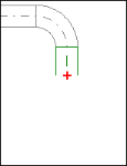
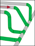
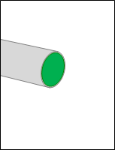
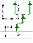
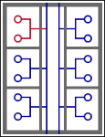
Typically, you start with the main pipes and the positions of the risers Simulate the consumer in this early stage using load objects in order to calculate the network in each processing step |
 . Then you can transfer the risers into the storeys
  .
. . Enter the estimated or roughly calculated demand value in these objects.
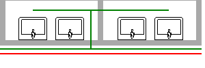
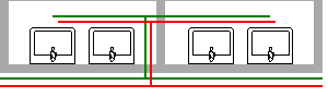
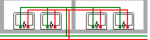
| Main lines and positions of the risers | First riser with a load object | Prepare risers for the entire storey | Transfer continuous risers to all storeys | Finish risers |
|---|---|---|---|---|
|
|
|
|
|
|
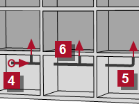
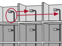
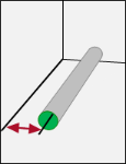
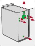
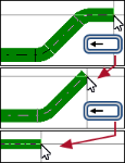
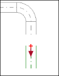
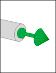
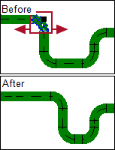
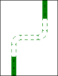
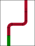
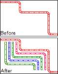
If the origin point of the network If you only know the riser point, first define only the vertical risers. In this case, move the network together at a later point. The order is irrelevant |
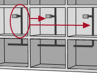
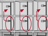
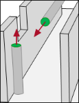
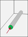
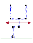
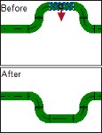
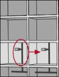
Open the next floor and take the first riser  Connect the load object Connect the load object  into the riser. into the riser. |
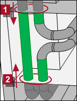
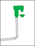
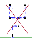
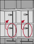
If you need further risers on this storey with the same medium and same dimension, copy the first riser using “Copy and Paste”. | The prepared risers of one storey can also be transferred to all storeys using “Copy and Paste”. Under the most favourable conditions, you only need one step for each storey. | Work manually with the end of the first riser (e.g. in the top floor). Then you can also transfer this constellation to all the other risers using “Copy and Paste”. |
|
See also |
See also |
See also |
See also |
 is known, start there with the pipework, move to the furthest rising point
  and end at the transfer to the next storey. Further risers
  can branch and also be transferred from there.
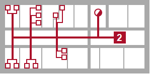
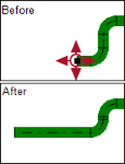
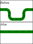
Refine the network construction
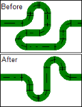
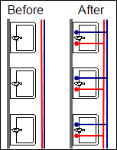
While advancing in the design process, you can refine the network construction on the storeys. You split the bigger load objects into smaller units with more accurate values and calculate the system again and again.
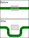
Remove the load object, connect earmarked objects
|
If the positions are earmarked objects |
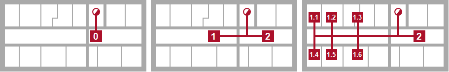
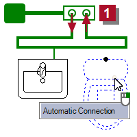
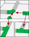
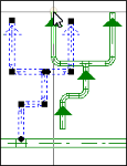
Systematic process when connecting objects
|
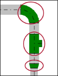
Step 1 You define the main pipes manually. If multiple pipes of different mediums run parallel to each other, you can make DDS‑CAD generate them automatically. |
|
Step 2 Also the distribution pipes of each medium are prepared manually. |
|
Step 3 A single distribution pipe segment can be copied and connected to the main system. |
|
Step 4 Finally, connect the objects using the automatic connection function. |
Special items in various networks
Specific characteristics must be considered for correct composition for the network with various media.
Remember to use insulation!
The pipework for the PWH Hotwater and PWH-C Circulation media must be completely insulated
DDS‑CAD checks the temperature of the PWH Hotwater medium and the environmental temperature which is predominant in the space. The insulation used determines the resulting temperature loss and influences the size of the pump. The rule is: the better the insulation, the smaller the circulating pump.
The insulation materials used are shown in the parts list and are displayed in the model using their thickness. This allows you to visualize the space needs for pipework.
No bypasses
The system cannot be calculated if there is a bypass in the pipe network.
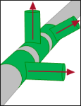
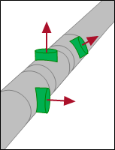
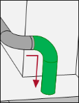
Correctly connect the circulation
|
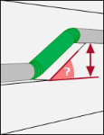
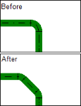
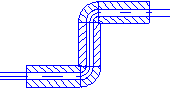
Move the PWH-C Circulation medium in such a way that the end meets a hot water line. The connection must be done in such a way that the PWH Hotwater medium flows through the T junction with no change in direction. |
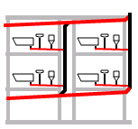
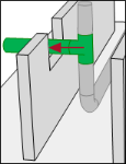
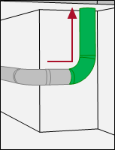
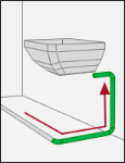
Correctly build the ring network
|
The pipework calculations include consideration of ring line systems. Always use an object from the Manifold Bind the point of use over a double-wall disk. Use the Automatic Connection function for this. Important! Only connect direct consumers (e.g. Water Tap) to the ring line. Devices for hot water production do not belong to a ring line |
Remember to use insulation!
The insulation materials used are shown in the parts list and are displayed in the model using their thickness. This allows you to visualize the space needs for pipework.
No bypasses
The system cannot be calculated if there is a bypass in the pipe network.
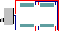
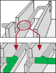
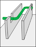
Correctly compose the pipe network for the “Tichelmann” system
|
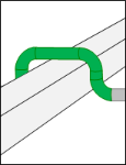
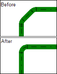
DDS‑CAD provides calculation of heating pipe networks which are designed in adherence to the “Tichelmann” system. Ensure that the supply and return are approximately the same length. |
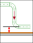
|
Always consider the slope from the start when constructing a waster water system. The setting is a prerequisite for the automatic connection of objects and pipe system calculation. |
Design pipeline
The construction of a pipe network is divided into three phases:
At the start you decide on the technical parameters and the direction of the first segment. Next, you define the course and eventually terminate the pipe. For each phase you can choose an appropriate operation depending on the situation.
 [D] /
[D] / 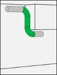
Insert fitting
Fittings and components are always inserted into an existing pipe system afterwards.
Select the desired description.
| Sprinkler | |
| Meter/Sensor/Recorder | |
| Pump | |
| Valve | |
| Filter/Opening | |
| Meter | |
|
|
Resistance Object |
Edit pipe system
You have many options to edit a pipe system afterwards.
Important!
If you shift a riser, then check the risers on the neighbouring storeys. The connected risers for all floors must stand superimposed over one another on all storeys after the operation is completed.
Operations and help functions for building a network
Various help functions support the construction of a pipe system. Take advantage of these functions when required.

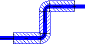
Configure presentation
Use the options in the View menu for situation-appropriate presentation of the pipe network.
| 2D Advanced pipe presentation | ||
|---|---|---|
| On |
|
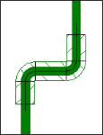
Pipework is displayed with nominal diameters and insulator thicknesses relevant to the selected materials. The representation shows the actual space needs. |
| Off |

|
Pipework is shown in one line. The medium is symbolized by color and line type. |
| Solid fill for ducts and pipes | ||
|---|---|---|
| On |
|
The lines are filled in with their color across the entire surface. |
| Off |
|
DDS‑CAD only shows the outer contours. |
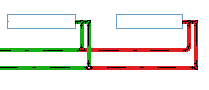
| Color Visualizes System State | ||||||||||
|---|---|---|---|---|---|---|---|---|---|---|
| On |
|
Colours show the status of a part of the system in regards to all defined limit values.
|
||||||||
| Off |
|
Colours show the medium. | ||||||||
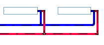
| Render using medium | ||
|---|---|---|
| On |

|
Colours show the medium in the rendered model. |
| Off |

|
The pipework shows in the rendered model in accordance with the materials used. |
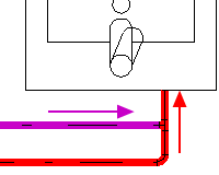
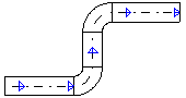
| Drawing direction (Arrows) | ||
|---|---|---|
| On |
|
The running direction is shown using arrows. |
| Off |
|
The running direction is not shown. |