IFC
If a project is running as a BIM process, exchange the data with the other project participants using the IFC format. The IFC import facilitates project work tremendously because from a single file the building model with all storeys, rooms and components is created automatically.
Important!
The focus of the IFC model is on information contained therein, and not on high quality representation. The building is visualized in three dimensions after import in DDS-CAD. The objects appear in their physical form and not as a simplified symbol. Thus, the presentation does not reflect mostly the usual norms and standards.
For the standardized representation of traditional 2D output for floor plans you can produce also DWG and DXF files.
Required conditions
- The building was modelled with classified 3D elements.
- Each object is assigned an unique identity.
- The building structure is mapped correctly, each room has been defined.
- The encapsulating objects are assigned to the rooms.
Workflow
Example
AS a basis for your work, you will receive an IFC model from the building at the beginning of the project. This IFC model you import as "Master".
Workflow
 Copy files into project
All data in a project must be part of the project folder. For this reason, save external data in the project folder before you carry out the import to DDS‑CAD.
Suppose you want to copy files quickly to the project folder without using other applications. A sub directory structure is not required.
When it concerns files with similar names, the original files are not overwritten. The date and time will be added to the original file name.
- In case you have received the files by e-mail: copy the attachment to a directory on the computer first.
- In DDS-CAD select Insert
 External Resource Copy Files to Project Folder. A dialog for selecting a file appears. You can select the following file formats: *.DWG; *.DXF; *.IFC; *.ZIP; *. PDF.
 - Open the path and select the file by double clicking
 . The file is copied to the project folder. In case you have selected a *.ZIP file, it will be extracted automatically. An automatic message will indicate this.
 - Click OK. You can run the import.
Suppose you work on projects with a large number of different files and you want to properly manage incoming and outgoing data. With the use of the Windows Explorer you can create a folder structure.
You can open Windows Explorer in DDS‑CAD and then open the project folder.
Select: Tools ![]() Open Folder
Open Folder ![]() Project
Project
 Import
- Open any storey of the project.
-
Start the function
 Imported files and model manager.
The dialog appears.
Imported files and model manager
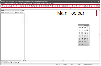
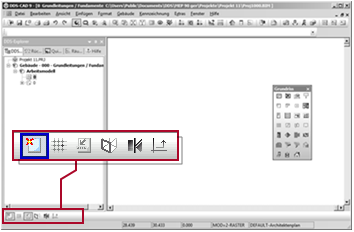
Select the function in Main Toolbar
- Activate the tab: IFC file Manager
- Click on the entry: Add file...
A dialog for selecting a file appears. - Select the desired file and click Öffnen. The dialog appears: IFC import...
-
Check the settings.
Setting Effect 
DDS‑CAD creates its own building model from the information of the imported IFC model at the same time.
Important!
The function uses the following quality characteristics for the IFC model:
- The building was modelled with classified 3D elements.
- Each object is assigned an unique identity.
- The building structure is mapped correctly, each room has been defined.
- The encapsulating objects are assigned to the rooms.

DDS‑CAD does not create a building model and instead adopts:
Choose this setting if in the current project you do not need a building model.
Example: If you only edit the lightning protection in the current project, then you only need the external building envelope. No complete building model is required for this.Level in the DDS-CAD model in which the lowest storey of the IFC model should be imported. By default DDS-CAD suggests the value 0. Enter a different number if you need an extra level in DDS-CAD below the lowest storey of the IFC file.
Suppose that the lowest storey of the IFC file is the basement. To illustrate the sewage pipes in the ground or the foundation you need to have a level for the foundations. Therefore, in this case, you set
 Start with DDS-CAD storey to the value 1. This way the lowest storey of the IFC file is imported into the DDS-CAD model 001. The underlying model 000 remains free for manual configuration.
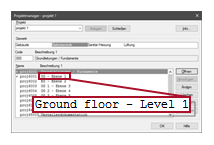
Display of the existing storeys in the IFC model and selection for the import according to DDS‑CAD. More
An IFC file contains all storeys by default. In case of incorrect settings in the IFC export (by the one why produced it), the model can contain wrong information that could be interpreted as a storey for the import to DDS-CAD. Common examples are sections, building elevations and part drawings. For the import to the DDS-CAD building model, these representation must be eliminated.Setting Effect
The storey is imported and creates a model in DDS-CAD.
The storey is not imported. Comparison of the storeys in the IFC file and the model in DDS‑CAD. You can compensate for errors in the IFC file during import to DDS‑CAD without modifying the IFC file.

Content, function IFC building Name of the building in the IFC file. Cells for information. No change is possible. IFC storey Name of the storey in the IFC file. IFC elevation Height of the storey in the IFC file. DDS-CAD description Name of the storey in DDS‑CAD. These fields are empty during an import into a new project because the storeys do not yet exist. DDS-CAD elevation Height of the storey in DDS‑CAD. These fields are empty during an import into a new project because the storeys do not yet exist. Import elevation Correction of the storey height for importing to DDS‑CAD. Change the value if IFC elevation displays no values or incorrect values.Cells for correction. DDS-CAD storey Correction of the storey sequence for importing to DDS‑CAD. Change the number if the storeys in the IFC file are not arranged in the correct sequence. - Click OK. DDS-CAD performs the import for all storeys.
 /
/ Example
At the beginning of the project, you imported an IFC model from the building as a "Master". If the architect changes its design, you get a new IFC model. In DDS-CAD, you update the existing "Master" IFC model.
Workflow
All data in a project must be part of the project folder. For this reason, save external data in the project folder before you carry out the import to DDS‑CAD.
Suppose you want to copy files quickly to the project folder without using other applications. A sub directory structure is not required.
When it concerns files with similar names, the original files are not overwritten. The date and time will be added to the original file name.
- In case you have received the files by e-mail: copy the attachment to a directory on the computer first.
- In DDS-CAD select Insert External Resource Copy Files to Project Folder. A dialog for selecting a file appears. You can select the following file formats: *.DWG; *.DXF; *.IFC; *.ZIP; *. PDF.
- Open the path and select the file by double clicking . The file is copied to the project folder. In case you have selected a *.ZIP file, it will be extracted automatically. An automatic message will indicate this.
- Click OK. You can run the import.
Suppose you work on projects with a large number of different files and you want to properly manage incoming and outgoing data. With the use of the Windows Explorer you can create a folder structure.
You can open Windows Explorer in DDS‑CAD and then open the project folder.
Important!
DO NOT overwrite the old file! Make sure the names of the old file and the new file are different.
Select: Tools ![]() Open Folder
Open Folder ![]() Project
Project
- Open any storey of the project.
-
Start the function
Imported files and model manager.
The dialog appears.
Imported files and model manager
Select the function in Main Toolbar
- Activate the tab: IFC file Manager
- Under
 Master IFC file click
  on the entry of the current IFC model. The context menu appears.
 - Select: Update / Replace...
A dialog for selecting a file appears. - Select the desired file and click Öffnen. The dialog appears: IFC import...
-
Check the settings.
Setting Effect
DDS‑CAD creates its own building model from the information of the imported IFC model at the same time.
Important!
The function uses the following quality characteristics for the IFC model:
- The building was modelled with classified 3D elements.
- Each object is assigned an unique identity.
- The building structure is mapped correctly, each room has been defined.
- The encapsulating objects are assigned to the rooms.
DDS‑CAD does not create a building model and instead adopts:
Choose this setting if in the current project you do not need a building model.
Example: If you only edit the lightning protection in the current project, then you only need the external building envelope. No complete building model is required for this.Level in the DDS-CAD model in which the lowest storey of the IFC model should be imported. By default DDS-CAD suggests the value 0. Enter a different number if you need an extra level in DDS-CAD below the lowest storey of the IFC file.
Suppose that the lowest storey of the IFC file is the basement. To illustrate the sewage pipes in the ground or the foundation you need to have a level for the foundations. Therefore, in this case, you set
Start with DDS-CAD storey to the value 1. This way the lowest storey of the IFC file is imported into the DDS-CAD model 001. The underlying model 000 remains free for manual configuration.Display of the existing storeys in the IFC model and selection for the import according to DDS‑CAD. More
An IFC file contains all storeys by default. In case of incorrect settings in the IFC export (by the one why produced it), the model can contain wrong information that could be interpreted as a storey for the import to DDS-CAD. Common examples are sections, building elevations and part drawings. For the import to the DDS-CAD building model, these representation must be eliminated.Setting Effect
The storey is imported and creates a model in DDS-CAD.
The storey is not imported. Comparison of the storeys in the IFC file and the model in DDS‑CAD. You can compensate for errors in the IFC file during import to DDS‑CAD without modifying the IFC file.
Content, function IFC building Name of the building in the IFC file. Cells for information. No change is possible. IFC storey Name of the storey in the IFC file. IFC elevation Height of the storey in the IFC file. DDS-CAD description Name of the storey in DDS‑CAD. These fields are empty during an import into a new project because the storeys do not yet exist. DDS-CAD elevation Height of the storey in DDS‑CAD. These fields are empty during an import into a new project because the storeys do not yet exist. Import elevation Correction of the storey height for importing to DDS‑CAD. Change the value if IFC elevation displays no values or incorrect values.Cells for correction. DDS-CAD storey Correction of the storey sequence for importing to DDS‑CAD. Change the number if the storeys in the IFC file are not arranged in the correct sequence. - Click OK. DDS-CAD replaces the entry in the dialog, updates the view on the screen and the building model.
Example
For coordination with the design of other disciplines, you can import any number of IFC models.
Workflow
All data in a project must be part of the project folder. For this reason, save external data in the project folder before you carry out the import to DDS‑CAD.
Suppose you want to copy files quickly to the project folder without using other applications. A sub directory structure is not required.
When it concerns files with similar names, the original files are not overwritten. The date and time will be added to the original file name.
- In case you have received the files by e-mail: copy the attachment to a directory on the computer first.
- In DDS-CAD select Insert External Resource Copy Files to Project Folder. A dialog for selecting a file appears. You can select the following file formats: *.DWG; *.DXF; *.IFC; *.ZIP; *. PDF.
- Open the path and select the file by double clicking . The file is copied to the project folder. In case you have selected a *.ZIP file, it will be extracted automatically. An automatic message will indicate this.
- Click OK. You can run the import.
Suppose you work on projects with a large number of different files and you want to properly manage incoming and outgoing data. With the use of the Windows Explorer you can create a folder structure.
You can open Windows Explorer in DDS‑CAD and then open the project folder.
Select: Tools ![]() Open Folder
Open Folder ![]() Project
Project
- Open any storey of the project.
-
Start the function
Imported files and model manager .
The dialog appears.
Imported files and model manager
Select the function in Main Toolbar
- Activate the tab: IFC file Manager
- Click on the entry: Add file...
A dialog for selecting a file appears. - Select the desired file and click Öffnen. DDS-CAD performs the import for all storeys.
- Click OK. The dialog is closed. You can continue with the next step.
Example
Suppose you have imported an "Coordination" IFC model into an existing "Master" IFC model. To avoid errors, check whether the positions of both models match. You may need to change the settings for the "Coordination" IFC model to match both models.
Workflow
You have several options for checking the correspondence between the imported IFC models.
-
Select a view that permits control of the situation.
More 
Front View 
Side View 
3D View (Camera) -
Choose a suitable perspective.
More- Point to the detail of interest in the model.
-
Click
, hold down the button and move the mouse. The model rotates with the mouse movement around a central point (indicated by a star). 
- Click on the model and hold the button for 0,5 seconds. DDS-CAD automatically switches to pan mode, in which you can move the model along the X and Y axis. The cursor symbol changes.
-
Move the mouse. The model changes its position with the mouse movement. The perspective of the model remains unchanged.

You can assign a pen to each "Coordination" IFC model. This makes it easier to distinguish the models.
-
Start the function
Imported files and model manager .
The dialog appears.
Imported files and model manager
Select the function inMain Toolbar
- Activate the tab: IFC file Manager
- In Allow select you can define the color. Select the cells by double clicking .The dialog appears: Attributes
- In
 Pen you select the desired setting.
 - Click OK. The model appears in the color of the selected pen.
By default, you only see the current storey of the "Master" IFC model. Frequently, a fully visible building facilitates the assessment of the situation.
-
Start the function
Imported files and model manager.
The dialog appears.
Imported files and model manager
Select the function in Main Toolbar
- Activate the tab: Ghost storey/discipline
The table lists all models of the active discipline - except the one that is currently opened. Column Show shows the status: The model is invisible.
 The model is visible.
 - Activate the desired model as visible. Click in column Show.
The symbol changes. -
Optionally, for better differentiation of storeys:
Check the settings.
Representation status of the ghosted model in the current model.
Setting Effect empty
The objects of the ghosted model use their original pens. 
The status indicates that all objects of the ghosted model use a common pen. The ghosted model is presented in a single color. Click
on an entry to open the context menu with further functions.Opens the dialog Attributes. You can individually define a uniform setting for the entire displayed model.
The ghosted model is uniformly assigned its default pen. An individual setting is disabled.
The uniform setting for the overall ghosted model is deleted. The individual object settings within the ghosted model apply.
Setting Effect
The ghosted model is displayed in dimmed/pale colors.
The ghosted model is displayed in normal colors. - Click OK. The selected model will appear in addition to the currently opened model.
There are several ways to correct the match between the imported IFC models.
Assume that a single "Coordination" model is moved away from the "Master" IFC model. In both models, you see reference points that are to be matched.
-
Activate Use Snap Points
-
Choose a suitable perspective.
More- Point to the detail of interest in the model.
-
Click
, hold down the button and move the mouse. The model rotates with the mouse movement around a central point (indicated by a star).
- Click on the model and hold the button for 0,5 seconds. DDS-CAD automatically switches to pan mode, in which you can move the model along the X and Y axis. The cursor symbol changes.
-
Move the mouse. The model changes its position with the mouse movement. The perspective of the model remains unchanged.
-
Start the function
Imported files and model manager .
The dialog appears.
Imported files and model manager
Select the function inMain Toolbar
- Activate the tab: IFC file Manager
- Click on the "Coordination" row of the IFC model. The context menu appears.
- Select: Move by Free Reference Point
The cursor appears as a crosshair. The information line shows: Choose Reference Point for Copy/Move - Click on the reference point of the "Coordination" IFC model. The cursor drags the end of a dynamic line. The information line shows: Choose Point to Move to
- Click on the "Master" reference point of the IFC model. Both models behave in the exact same way.
Suppose, you have imported several "Coordination" IFC models, which behave in the same way as one another. However, there is a difference to the "Master" IFC model. In this case, you can correct the reference point for all "Coordination" IFC models.
-
Start the function
Imported files and model manager .
The dialog appears.
Imported files and model manager
Select the function inMain Toolbar
- Activate the tab: IFC file Manager
-
Check the settings in
Coordination filesGlobal settings for the imported models in
Coordination files.
Content, function X / Y / Z Coordinates of the global reference point. By clicking on the cell you can change the value by manual input.Rotation Rotation of the plane on which the models Coordination files stand in. By clicking on the cell you can change the value by manual input.Reference storey Selection of the storeys to which the models
Coordination files refer.By default, the lowest storey of the DDS-CAD project is used as a reference for importing an IFC model. You may be given a model with the lowest storey missing. The imported model appears in DDS-CAD on an incorrect storey. In this case, define another storey as a reference.
- Select the cells by clicking . The entry appears as a selection menu.
- By clicking on
 you can define a different storey as a reference. The effect is immediately visible.
 - Check the result.
- Select the cells by clicking