Ventilation system design
We describe possible strategies to build, edit and develop a network in a step-wise fashion in a building with several storeys.
For the described actions, open a model of the discipline Lüftung.
General procedure
To make the job effective, consider the space requirements of the system from the beginning. Work with the expected dimensions, and think about insulation as well as possible size changes using a network calculation.
 More
MoreWorking in the manhole
|
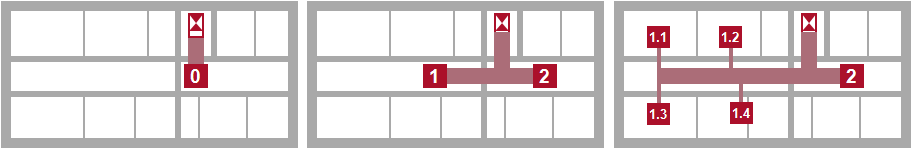
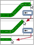
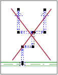
The positions of the ventilation centre and manhole are set with the complete building design. You know how to measure the total air volumes and can measure the cross section of the main channels with this. You develop the network in a step-wise fashion using these assumptions. Simulate the consumer in this early stage using load objects in order to calculate the network in each processing step |
 . Enter the estimated or roughly calculated demand value in these objects.
| Prepare the positions in the manhole | Take to the first storey, use a load object | Transfer to the following storeys | |||
|---|---|---|---|---|---|
|
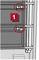
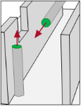
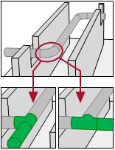
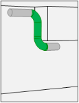
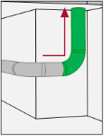
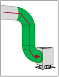
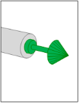
Start a ventilation duct for each medium starting with the ventilation central equipment room, lead it to a shaft and transfer it to the next storey  . . |
|
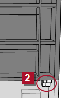
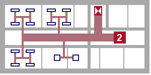
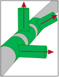
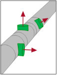
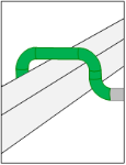
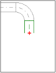
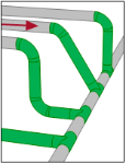
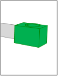
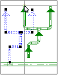
Open the next storey and take all  media into the continuous ventilation duct. Produce a branch and end it with a load object media into the continuous ventilation duct. Produce a branch and end it with a load object  in order to prepare the distribution on the storey. in order to prepare the distribution on the storey. |
|
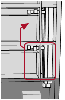
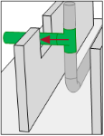
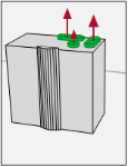
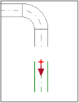
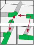
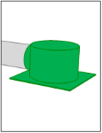
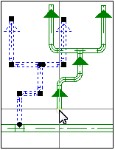
You can transfer the prepared ventilation ducts of one storey to all floors using Copy and Paste. You also take over the connected load objects and correct their discharge units to the conditions of the respective storeys. |
|
See also |
See also |
See also |
|||
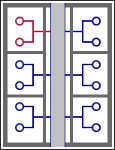
Refine the network construction
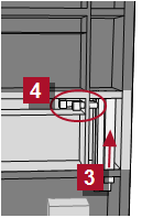
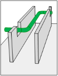
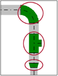
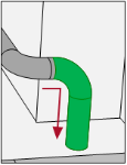
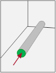
While advancing in the design process, you can refine the network construction on the storeys. You split the bigger load objects into smaller units with more accurate values and calculate the system again and again.
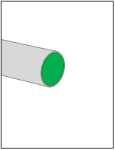
Remove the load object, connect objects with a dedicated purpose.
|
If the positions of the objects with a dedicated purpose |
Design ventilation system
The construction of a duct network is divided into three phases:
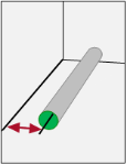
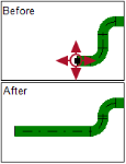
At the start you decide on the technical parameters and the direction of the first segment. Next, you define the course and eventually terminate the duct.
For each phase you can choose an appropriate operation depending on the situation.

Insert object in duct
These objects are always inserted into an existing pipe system afterwards.
Select the desired description.
| Transition | Access Door | |||
| Attenuator | Sample | |||
| Damper | Heating Coil | |||
| Grille |
|
Cooling Coil | ||
| Accessory | Fan | |||
| Heat Exchanger | Resistance Object | |||
| Filter |
Edit ventilation system
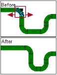
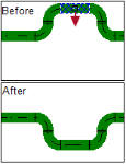
You have many options to edit a pipe system afterwards.
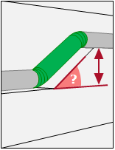
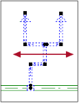
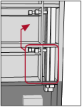
Important!
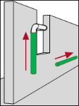
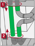
If you shift a riser, then check the risers on the neighbouring storeys. The connected risers for all floors must stand superimposed over one another on all storeys after the operation is completed.
Operations and help functions for building a network
Various help functions support the construction of a pipe network. Take advantage of these functions when required.
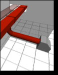
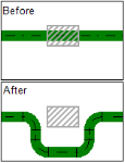
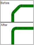
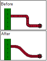
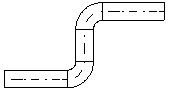
Configure presentation
Use the options in the View menu for situation-appropriate presentation of the pipe network.
| Advanced Representation | ||
|---|---|---|
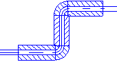
| On |
|
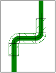
Pipework is displayed with nominal diameters and insulator thicknesses relevant to the selected materials. The representation shows the actual space needs. |
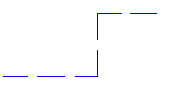
| Off |
|
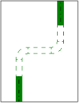
Pipework is shown in one line. The medium is symbolized by color and line type. |
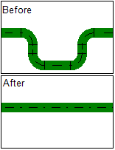
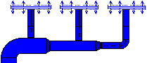
| Drawing direction (Arrows) | ||
|---|---|---|
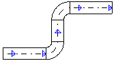
| On |
|
The running direction is shown using arrows. |
| Off |
|
The running direction is not shown. |
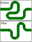
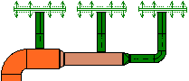
| Color Visualizes Velocity Level | ||
|---|---|---|
| On |
|
Colors visualize the association of a system part to a speed level. |
| Off |
|
Colors show the medium. |
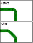
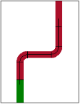
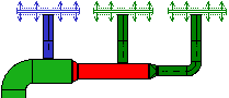
| Color Visualizes System State | ||||||||||||||||||
|---|---|---|---|---|---|---|---|---|---|---|---|---|---|---|---|---|---|---|
| On |
|
Colors show the status of a part of the system in regards to all defined limit values.
|
||||||||||||||||
| Off |
|
Colors show the medium. | ||||||||||||||||
| Color Visualizes System State | ||||||||||||||||||
|---|---|---|---|---|---|---|---|---|---|---|---|---|---|---|---|---|---|---|
| On |
|
Colors show the medium.
|
||||||||||||||||
| Off |
|
Colors show the medium. | ||||||||||||||||
| Drawing direction (Arrows) | ||
|---|---|---|
| On |
|
The running direction is shown using arrows. |
| Off |
|
The running direction is not shown. |