Pipework – Course
Insert fitting
Example
|
Suppose you want to use a component and configure specific settings at a particular position during the construction:
|
Workflow
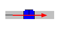
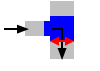
- Move the pipe to the position for inserting an object.
- Define a fix point by clicking
 .
. -
Select the object from the context menu (click
 ) or by using a
  keyboard key. The dialog appears.
 -
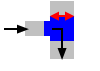
Check the settings.
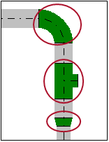
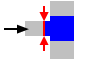
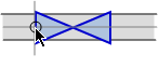
Bend
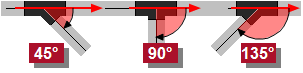
 Angle
Angle
Angle of the direction change.
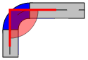
 Left / Right / Up / Down
Rotation of the bend and further direction of the pipe. The setting is usually set during the drawing of the pipe and also defines the angle at
Rotation.Setting Example Left 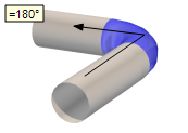
Right 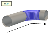
Up 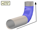
Down 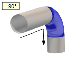 Rotation
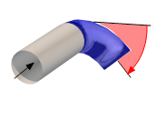
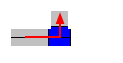
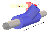
Rotation of the object in degrees (°) around its center axis. A positive angle causes a rotation to the right (relative to the drawing direction).
The value is usually set during the definition of the course. A manual entry is required if the rotation has to deviate from the perpendicular angle.
 Angle to X-axis
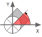
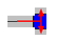
The settings are only available for objects in vertical segments. The rotation of the component is defined as angle. At an angle=0, the object is rotated to the right and corresponds to the position of the X-axis. A positive rotation causes the component to rotate counter clockwise.
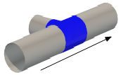
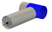
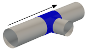
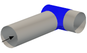
 Tee
Straight / Branch / Ahead
Tee
Straight / Branch / Ahead
Setting Effect Straight An exit shows the selected direction. The pipeline runs straight ahead.
Branch An exit shows the selected direction. The pipeline follows the branch.
Ahead Two exits are on the right and left. The pipeline follows the branch of the selected direction.
 Angle
Angle
Angle of the branch with respect to the pipeline.
 Left / Right / Up / Down
The setting also defines the angle at
Rotation of branch.Setting Draw direction Straight / Branch AheadLeft =180°
Right =0°
Up =270°
Down =90°
 Rotation of branch
Rotation of the object in degrees (°) around its center axis. A positive angle causes a rotation to the right (relative to the drawing direction).
The angle is automatically set with
Left / Right / Up / Down. A manual entry is required if the rotation has to deviate from the perpendicular angle.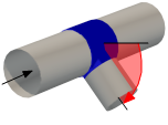 Angle to X-axis
The settings are only available for objects in vertical segments. The rotation of the component is defined as angle. At an angle=0, the object is rotated to the right and corresponds to the position of the X-axis. A positive rotation causes the component to rotate counter clockwise.
 Entry /
  Branch / Exit
Nominal diameter of the connections. The meaning depends on the selected setting at Draw direction.
Properties Draw direction Straight / Branch Ahead Entry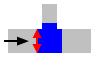
 Branch
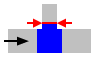
 Exit
Exit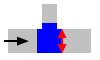
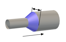
 Transition
Outgoing
Transition
Outgoing
Dimension of the pipe after the transition.
 None / Line / Arrow
The setting affects the display of the symbol if the pipes are presented as a line. (The option View
 Advanced Representation is deactivated.)
Setting Effect None 
Line 
Arrow 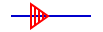
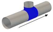
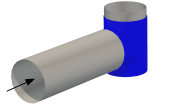
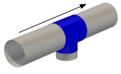
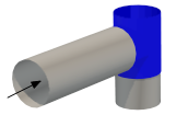
 Insert centered
Example: Valve
Setting Effect
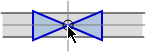
The symbol is centered.

The symbol is passed to an end.
Rotation
Rotation of the object in degrees (°) around its center axis. A positive angle causes a rotation to the right (relative to the drawing direction).
 Angle to X-axis
The settings are only available for objects in vertical segments. The rotation of the component is defined as angle. At an angle=0, the object is rotated to the right and corresponds to the position of the X-axis. A positive rotation causes the component to rotate counter clockwise.
- Click OK. The object is a part of the pipeline. It defines the direction and characteristics of the continuing pipe at the exit of the object.
 [B]
[B]