| ◄► |
|
||||
|
|||||
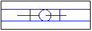
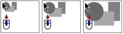
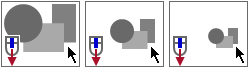
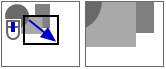
Insert object in horizontal duct segment
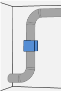
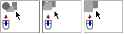
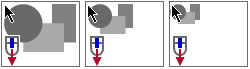
Insert object in vertical duct segment
|
Example Suppose you want to simulate the resistance of a complex assembly by a resistance object in a vertical ventilation duct. Objects in vertical ducts are visible in three-dimensional views. |
Workflow
Select: Duct Network ![]() Components
Components ![]() Resistance Object
Resistance Object
The cursor moves the object.The information line shows:[Click Left] at segment=Position to insert
-
Apply a sufficient zoom level -
 zoom.
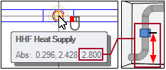
zoom.DDScad symbolizes a vertical pipe as a circle with the dimension of the nominal diameter.
-
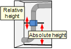
Point into the circle. The circle appears as a marked object. DDScad displays the information about the pipe and the current position. The displayed height corresponds to the center of the vertical section, measured from FFL.
- Click
 . The dialog appears: Give position in flow segment
 -
Define the installation height.
- Click OK. The dialog appears: Resistance Object
 of the mouse
 You may occasionally receive drawings in which individual fragments are positioned outside the floor plan. This means that the actual drawing after calling the function
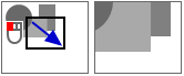
Check the settings.
 Pressure loss by
| Setting | Effect |
|---|---|
| zeta-value | DDScad enables  Zeta for entries and calculates the value in Zeta for entries and calculates the value in  Pressure loss. Pressure loss. |
| preset | DDScad enables Pressure loss for entries and calculates the value in Zeta. |
/ Zeta
Effective pressure loss coefficient of the illustrated assembly.
/ Pressure loss
Complete pressure loss over the illustrated assembly.
Length
Length of the symbols. You can use different unit of lengths.
 Turn direction
The setting applies to objects with an indication of the direction.
|
Example: Fan |
||
|---|---|---|
| Setting | Effect | |
|
|
|
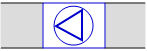
The object is reversed when inserted. |

|
|
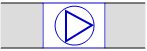
The object is inserted in the original direction. |
Click on OK. The object is part of the pipe network and remains active with the current settings. You can insert the object again at a different position.