You are to make a heat requirement calculation for a building. Perhaps you know the layer structure in walls, floor and roof, but not the U value? No problem. DDS-CAD has a function to help you calculate.
After having defined a building by means of the DDS-CAD room module, or after the import of an IFC file, you can get hold of each single building object, in order to calculate the U value - assuming that you know which layers the objects have been built of. From the function Building dialog you will see a flag named "U value".
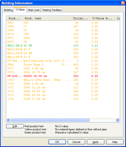
List of building objects in your project.
The objects in the list will get different colours, depending on the U value having been calculated or not calculated.
Red colour: The objects are not calculated, and there are no U value from the product database
Yellow colour: The objects are not calculated, but there is an U value from the product database
Green colour: The objects are U value calculated, or entered manually.
In the DDS-CAD product database there are predefined layers. These layers hold information about specific weight (material density with the designation kg/m³) and heat conductivity (λ = W/mK). The formula for U value calculation reads: U = 1/Rtotal where Rtotal is the sum of thermal resistance from all layers. Further R= d/λ where d= material thickness and λ is thermal conductivity.
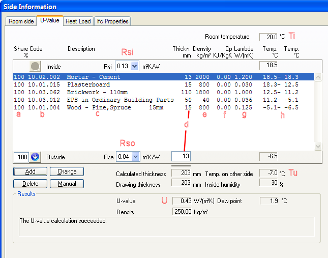
List of layers defined in DDS-CAD. Top = inside, bottom = outside
|
a = percentage of wall (see later in this chapter) b = code c = layer description d = layer thickness in mm e = specific weight f = specific heath capacity g = heath conductivity λ |
h = temp. difference through layers Ti = inside temperature Tu = outside temperature Ri = inside resistance number Ru= outside resistance number U = calculated U value |
See video how to define layer in a wall, to end up with an U value of 0.36 W/m²K
Sometimes the building components are divided, i.e. not uniform. A typical example could be a wall in a wooden house with one part joists and one part insulating mats. In this case the percentage of each layer must be entered. If a percentage is entered in one layer, the same must be entered for all the others.
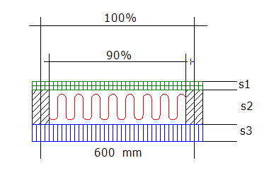
The figure above displays a wall section consisting of plaster (s1), mineral wool + joists (s2) and wooden cladding (s3). The share of mineral wool is 90%, and all layers must therefore be divided into 90% + 10%.
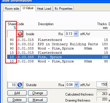
The same wall in DDS-CAD U value calculation. 90%+10% plaster, 90% idler roller + 10% pine(joist) and 90%+10% wood at the outside.
The dew point of the building object has been calculated if the relative humidity inside the building is set. Set relative humidity from the Room list.
See video how to enter relative humidity in a room.
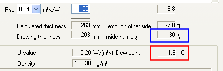
Dew point on the inside of a wall when relative humidity in the room is 30%
< Previous Chapter - Next Chapter >
