In this chapter we deal with nominal and balanced pressure loss calculation, and automatic dimensioning of duct systems
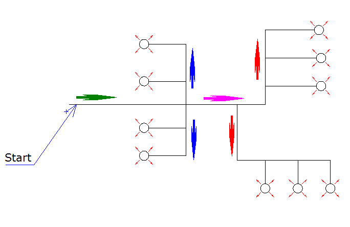
Based on the air quantity entered for valves in a ventilation system (hereafter called system), DDS-CAD will sum up and calculate air quantity, speed, nominal pressure loss and balancing. You must enter a calculation point in the duct net where you want the calculation to have the basis. From this point DDS-CAD will calculate to all the sub strings in the system and sum up the properties.
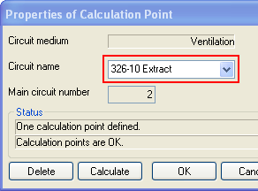
A calculation point must be defined in order to create a system. From this point DDS-CAD will get info from all valves connected to the system, and sum up based on the calculation point.
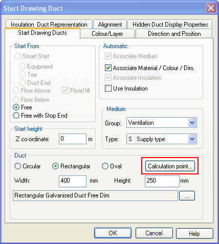
When you have finished defining the ventilation system, you should give it a name. Double-click on the duct from where the calculation should start, and press the button "Calc. Point"
|
|
If the duct is started from Free, free with Stop End, Object, Hole in stop end or another storey does mot influence the calculation. What is important, is that the calculation point is defined in a Duct Start and not in a Duct End. You can define as many calculation points as you want in a system. DDS-CAD will always have the basis in the duct start where you define the point and calculate from this.
The calculation name is free, and this is the name the system will get. By a possible IFC export, this system will be exported as an IfcSystem. |
See video how to insert a calculation point and give it a name "362-10-Supply air"
Start the calculation from the Building dialog on the tab Pressure loss calculation. Here all the calculation points you have created in this project are listed. Select the calculation you want to start, and press Calculate
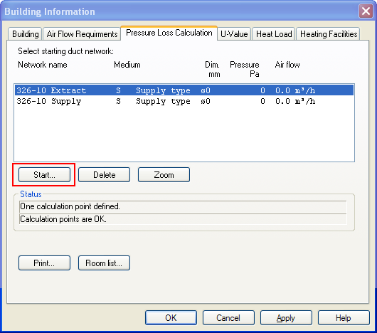
The Pressure loss calculation tab will display all calculation points defined in an active project.
When you start the calculation, the nominal calculation is displayed. All sub strings are listed, and you can read information about them from the list.
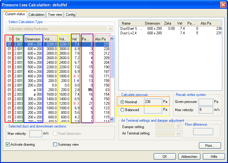
Drawing no. /Storey: A system can go through several storeys. This column displays which drawing number this sub string belongs to.
String no. : All sub strings get individual numbers. They are numbered sequentially.
Dimension: Start dimension for every sub string
Nominal air quantity: The total nominal air quantity through the sub string
Balanced air quantity: Displays the balanced air quantity through the sub string (balanced calculation has to be performed in advance)
Velocity: Air speed for every sub string is calculated from air quantity and dimension
Pressure loss over sub string: The pressure loss over sub string.
Total pressure / residual pressure: Displays total pressure by selected sub string. In cases where a sub string ends in a valve, the residual pressure on the valve is displayed. Therefore, there will always be at least one valve with a residual pressure = 0.
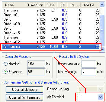
As mentioned, all sub strings are listed on the left side of the dialog. The right side displays which components each sub string consists of.
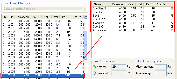
The example above shows that sub string 01.2.006 starts with a DuctStart, a string of Ø100 duct, a bend, a transition to Ø160 before terminating with an air terminal.
The pressure loss over components is based on Zeta values. These Zeta values are automatically calculated.
See documentation for automatic calculation of Zeta values.
When the pressure loss calculation starts, it will always be in "nominal mode". If you press the radio button for Balanced, DDS-CAD will calculate the real air quantity for all sub strings. Basically all dampers and valves will be open, and you will see the difference in the columns Q Nom. and Q Bal.
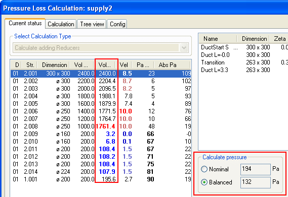
After the radio button Balanced has been selected, QBal is listed with different air quantity values from QNom.
When balancing is performed, you may see some air quantity values with red values and some with blue. These colour codes indicate either too high or too low air quantity based on the nominal value. The limit value for divagation is set under the tab "Config"
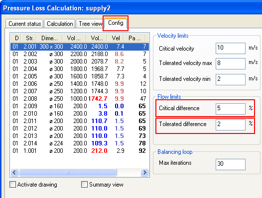
The "Config" tab in the fields under Quantity limit. If Critical difference is exceeded, the colour in the column with balanced air quantity turns dark red if too much air, and dark blue if too little air. If the difference is between Tolerated difference and Critical difference, the colours will be light red and light blue.
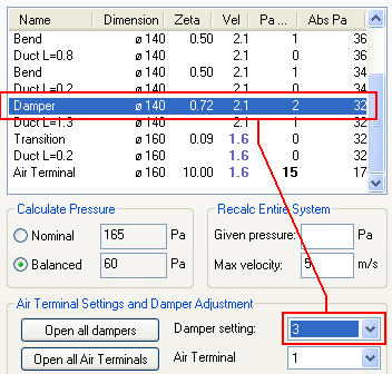
When balancing is finished, and you see that you must adjust the system, this can be done with two types of components - adjustment damper or valve. You can adjust either manually from the model, from the pressure loss calculation, or you can let DDS-CAD do it for you.
|
As a result of the change in dimension, the pressure in the system will also be changed. Note that the air quantity for balancing is changed. If you want DDS-CAD to change dimensions and insert reducers, press the button Update at the bottom to the right.As a result of the change in dimension, the pressure in the system will also be changed. Note that the air quantity for balancing is changed. If you want DDS-CAD to change dimensions and insert reducers, press the button Update at the bottom to the right. |
|
In the component list for sub strings you will see, that if there is a valve or damper in the list, it can be throttled further down.
See video how to change damper control in the DDS-CAD pressure loss calculation manually
As you may have noticed, manual regulation is time consuming, at least for larger systems. DDS-CAD can do the job for you and make sensible suggestions, assuming that you have inserted dampers in the proper places.
In the flag "Calculation" three types of calculations can be performed. Calculate with reducers, calculate without reducers, and adjust valves and dampers
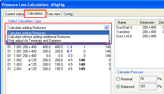
3 different calculations under the tab "Calculation".
Calculate adding reducers: Dimensions the system according to speed criteria set in the flag "Setup" . Inserts reducers when necessary
Calculate without adding additional reducers: Same as above, but no reducers are inserted. Adjust existing reducers, and branch dimensions on holes/tees.
Only adjust Air Terminals and dampers: Automatic regulation of dampers and valves to obtain the balanced air quantity within the criteria set in the flag "Setup"
If you select one of the two dimension calculations, parts of the column with dimensions will change colour from black to green.
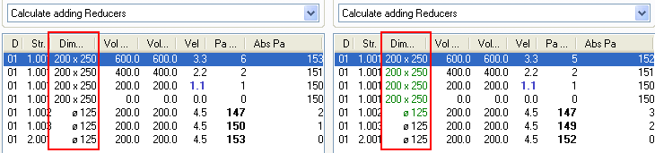
The dimension row is changed if calculation with dimension change is activated. The dimensions DDS-CAD want to change will get green colour. The dimensions not changed will remain black.
As a result of the change in dimension, the pressure in the system will also be changed. Note that the air quantity for balancing is changed. If you want DDS-CAD to change dimensions and insert reducers, press the button Update at the bottom to the right.
If there are parts of the systems that you do not want DDS-CAD to change, you can tick off in the check box "Fixed dimensions". Select the sub string in the list for which you want a fixed dimension, and click in the check box. The dimension will then be fixed until the end of the duct.
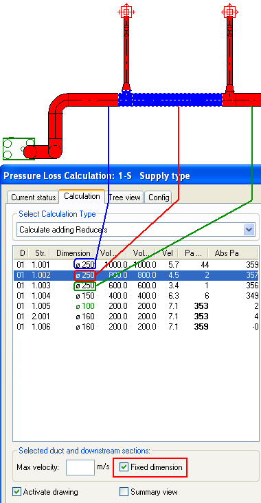
Fixed dimensions are activated. The 2 sub strings belonging to the main string will remain Ø250 until the duct end.
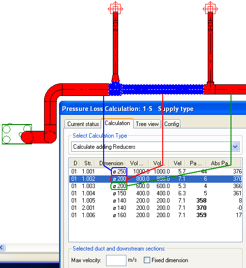
Fixed dimensions are not activated. DDS-CAD will not adjust the sub string 1 to Ø200, while the last sub string gets the dimension Ø200.
Dimensions, Config
In the tab "Config", velocity criteria for dimensioning can be set. In addition, criteria for dimensions max and min can be set for both circular and rectangular ducts.
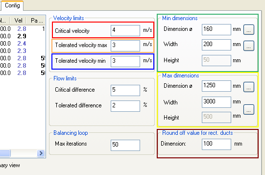
Velocity limits:
Critical velocity - if the velocity exceeds this value, the value field in the velocity column turns dark red
Tolerated velocity max - if the velocity exceeds this value, but not the critical velocity, the value field in the speed column turns light red
Tolerated velocity min - if the velocity is less that this value, the value field in the velocity column turns dark blue.
Min dimensions - by automatic dimensioning the minimum dimensions can be decided here. At the top for circular ducts, the next two are width and height for rectangular ducts.
Max dimensions - by automatic dimensioning the maximum dimensions can be decided here. At the top for circular ducts, the next two are width and height for rectangular ducts.
Round off values for rectangular ducts - by automatic dimensioning for rectangular ducts, round off value is set. In this manner DDS-CAD will suggest your default dimensions. (Ex: DDS-CAD will then not suggest to change a rectangular duct to dimensions 428x367 mm)
See video how to set Critical velocity to 4 m/s, max tolerated velocity to 3m/s, min velocity speed to 1 m/s, minimum dimension to Ø160, max dimension to Ø500.
By clicking the right mouse button on a component at the right, you will get some options.
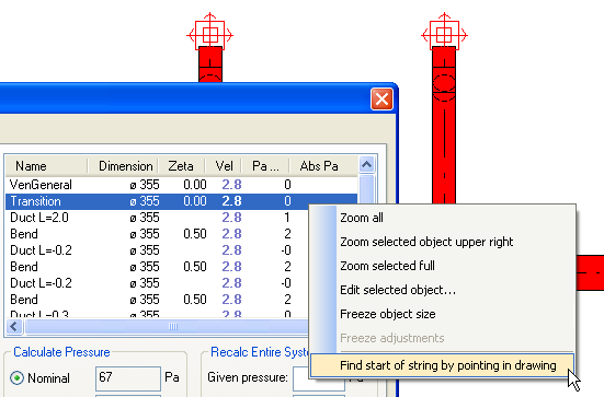
Zoom all - zoom the entire model adapted to your screen
Zoom selected object at the upper right - zooms in selected object to position at the top to the right on your screen.
Zoom selected full - zooms the selected object to fill your whole screen.
Edit selected object... - gets the property dialogue box for the object
Freeze object size - locks the dimensions to the object for possible automatic dimensioning later
Freeze adjustments - for dampers and valves the adjustment (throttle) can be locked
Find string start by pointing in the drawing - If you want to look closer into the pressure loss calculation for a sub string in the model, click on the duct.
To make a report from the calculation, select the flag "Current status" and press the button "Print". Then select the report setup you want to use.
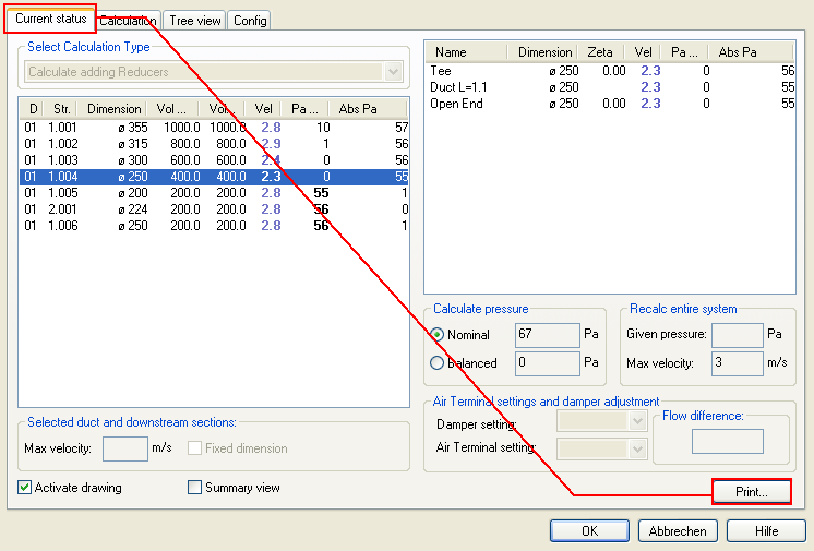
The tab Current status and Print - to make a report.
Click here to see a finished report
When you have performed a DDS-CAD pressure loss calculation, you can text ducts and components with calculation data. This can be data such as pressure, air quantity, speed and regulation for dampers and valves. Indicate the component you want to text and press the button "Part text"
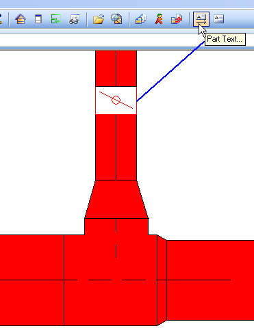
Indicate first what you want to label , then select Part text.
The Part text function can have many individual defined setups.
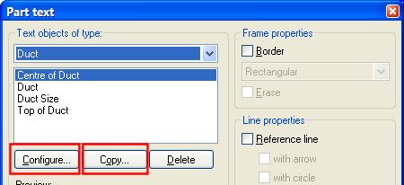
Individual setup for text. Press Copy, enter a description for the setup. Then press Configure...
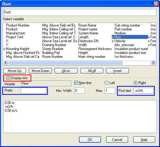
Individual setup for text. Select the information you want from the list, then press "Display info". If you want pre and post text, write in the blue fields.
See video how to define setup and text a damper.
Note: If you want to text air quantity/speed on ducts and components, the calculation in which you were working when finishing the pressure loss calculation will be in force. This means, if you have ended the calculation in "Balanced" mode, the balanced value is displayed. The same goes for "Nominal" mode.
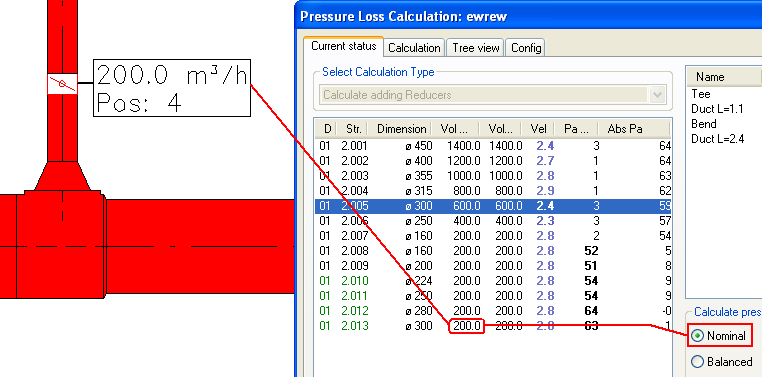
Damper labelled after finishing the calculation in Nominal mode.
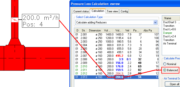
Damper labelled after finishing the calculation in Balanced mode.
As previously written, the pressure loss calculation is based on zeta values for components (except straight ducts). If you know the pressure loss in Pascal over a component with a certain air quantity, you can let the DDS-CAD Zeta calculator help you. Get the zeta calculator by double-clicking on the component you want to edit, and select the tab.
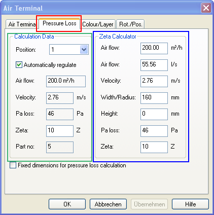
Zeta calculator for an air terminal.
If you select the tab Pressure loss you can, in the fields for Zeta calculator enter Pa loss and get a Zeta value at the bottom. This Zeta value you can transfer to the field Zeta to the right.
See video how to calculate the zeta value for a valve with pressure loss of 60 Pascal with air quantity 130 m3 per hour.
< Previous Chapter - Next Chapter >