Create own DDS-CAD objects for HVAC
1. Defining 2D and 3D symbol, save them at user directory
2. Make connection points to pipe and duct attachment. Find and read DDS-CAD dat files.
3. Add object to DDS-CAD product database
4. Set colour and render mapping information
5. Create Air Terminals / Grille
6. Use existing DWG file to make DDS-CAD obejct
7. Insert bitmap preview, URL reference to product sheet
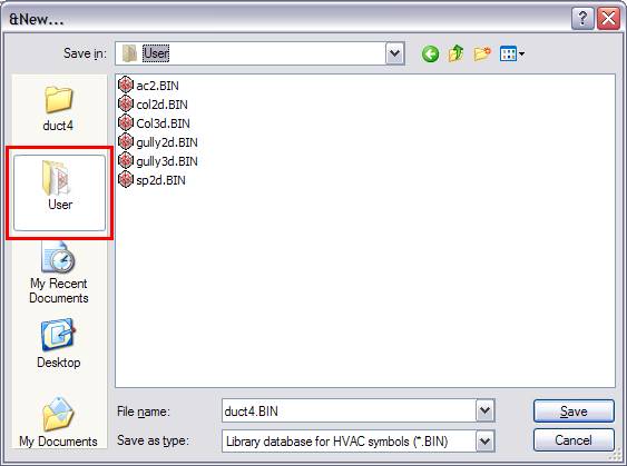
DDS-CAD objects need a 2D symbol and a corresponding 3D symbol. DDS-CAD will automatically change between these symbols when changing view from 2D to 3D presentation in the model. The symbol has to be in DDS-CAD User directory. If you are using Windows XP or Windows Vista, you will see a User icon at the left hand side at “Open” or “Save as” dialog.
Find the DDS-CAD User directory.
To create a symbol, press “OK” at the Project Manager, go to “File” and “New” .Give the name of the symbol, correct database and press “Save” .
Once you have created the symbol, you can start to draw the contents. Make sure of where the symbols origo is, because this will be the insert point of the symbol. The origo has coordinates X=0, Y=0 and Z=0. When you create a symbol, you will see the origo as a small cross at the lower left side of drawing.
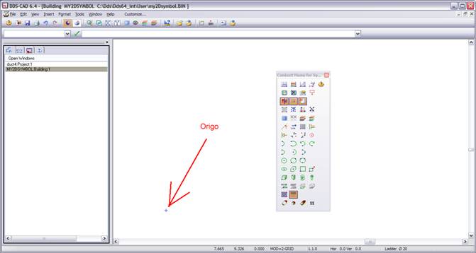
The origin of the symbol drawing.
Draw the rectangle, lines, circles or whatever your symbol consist of. You are always able to set exact placement of every geometric object by changing the MO command in front of the geometric command.
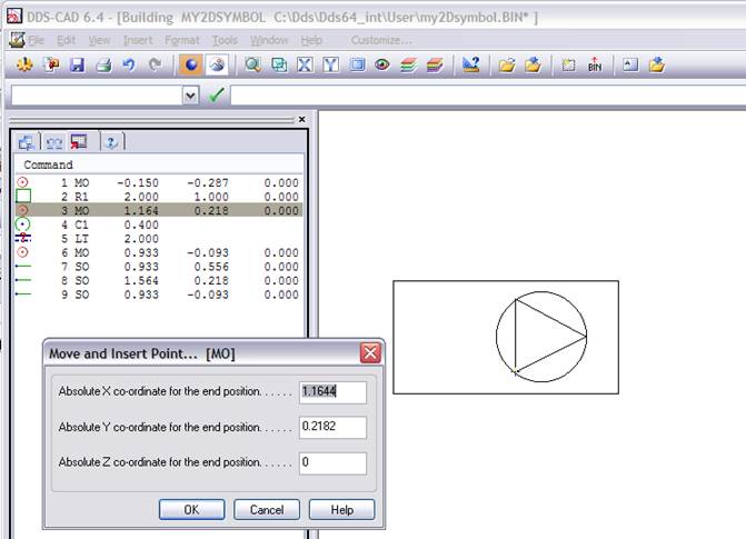
Changing the placement of geometric objects.
Once you are finish with the 2D symbol, save the file, and do the same procedure to the 3D symbol.
The command for connection points are IP . First set the point where you want the connection then type IP to your command line. IP has 4 parameters. They are:
1: R.Type – medium type of connection (read from your dat file)
2: Dim – Dimension of connection (in mm)
3: HorDir – direction in horizontal plane (in degrees)
4: VerDir – direction in vertical plane. (in degrees)
To find your medium type, you have to open the dat file. DuctWork dat file is named Ven-Cod.dat while PipeWork dat file is named Hcs-Cod.dat.
Dimension is in mm. If you want to make a DuctWork rectangular connection, type the width and height separated by . (for example 800.300).
To find your dat files, go to menu Help -> Information and click at the tab DDS-Info
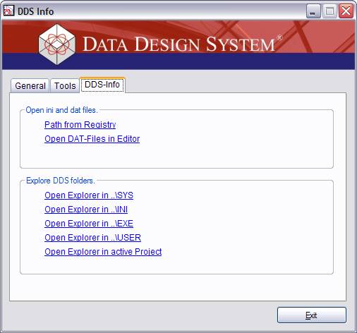
DDS-Info from help menu.
Click at the “Open DAT-Files in Editor” link, and you will be able to open wanted dat file.
The direction from connection point is in degree from 0 to 360. 360 is along positive X axis, 90 are along positive Y axis etc.
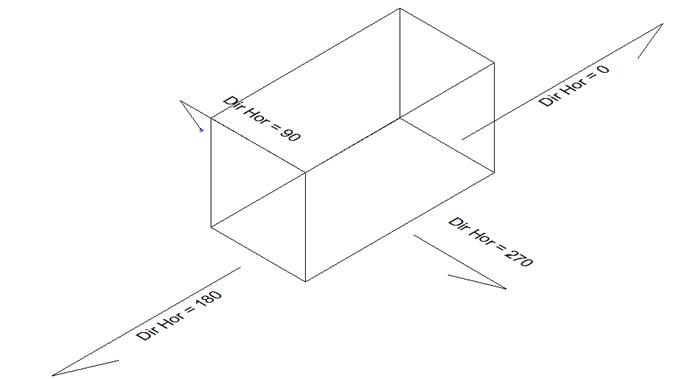
Direction of horizontal connect.
The vertical option work the same way. 0 is a horizontal connection, 90 are positive along the Z-axis and 270 are along negative Z-axis.
In our example, we will make 4 connection points. One Duct Work Supply Air with dimension 850x 300 and horizontal direction 360 degrees. One Duct Work Extract Type with dimension 850x 300 and horizontal direction 180 degrees. One Pipe Work Flow Cooling point with dimension 20 and horizontal direction 270 degrees and finally one Pipe Work Return Cooling point with dimension 20 and horizontal direction 270 degrees.
These connection points have to be created both in the 2D and 3D symbol at the same place.
From our Duct Work dat file (Ven-Cod.dat) you can read that the Supply medium has number 10, Extract medium has number 11. From our Pipe Work dat file (Hcs-Cod.dat) you can read that the Flow Cooling medium has number 18, Return Cooling medium has number 19.
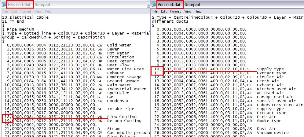
Dat files. Left side show Pipe Work where medium numbers are at first column. Right side show the Duct Work mediums.
Start at the 2D symbol. Set first point, then type the IP command. Afterwards you can adjust the points in X, Y and Z direction.
Do the same with the 3D symbol. TIP! To avoid making IP points twice, you can do the 2D symbol stuff, make IP points and save the symbol.
Then change the 2D geometric objects to 3D geometric objects, and save symbol file as your 3D file.
Our example is an AHU (Air Handling Unit), and belong to the Duct Work application. Open a Duct Work model, find AHU from tool box and browse to where you want your new object. Right click at an existing product, choose Copy. At the new object, right click and choose Change.
In this properties, give a suitable description, and give the name of your new object in the “Extern Symbol” field. Give first the name of the 2D symbol, then the name of the 3D symbol. Separate then with semi colon ( ; ) and remember to write the extension (.bin) Press OK and your new object is ready to use. If you want to use this in other projects, right click at your new object, and choose Admin.
If you want different colours and render mapping ID’s to your symbol, it’s possible to insert those after the symbol is made. The colour command is LG while the material map ID command is IM.
First let us change the colour at the 3D symbol. The circle and arrow we change to red, and the box we want to be black. In Quick Edit registry, right click at the geometric object that should change, and choose Insert. Give the command LG, press OK, and Repaint the screen. Right click at the LG command and choose Change. Set the colour command in front of all geometric objects you want to change.
The render mapping ID command is IM. This has 3 parameters. First is application code (1= building, 6=electrical, 7=Duct Work and 8=Pipe Work)
Second parameter is component, and for DDS users this is 998. Last parameter is ID code. Here you are free to set a number from 0 to 999. After this, the mapping file has to be updated.
To our 3D symbol, we set the material ID to the circle to 7 – 988 – 400 and the box to 7 – 988 – 401
Next is to map the IM to material or colour. Set render mode, Edit Material Map and map the two new ID’s to a material or colour.
Due to a provisional limitation to DDS-CAD, you can’t give Air Terminal free names. It has to be a system name. The rules are GV2xxx.bin to 2D symbol and GV3xxx.bin to 3D symbol. xxx is the symbol number and varies from 000 to 999. Customer made Terminals have the range from 500 to 599 to use. After making the symbol, use same procedure to add it to the product database. Only difference is to give the symbol number instead of the symbol name.
If you have a set of DWG/DXF figure files, and want to use them as DDS-CAD objects, it takes only a few steps to get there. First, you have to convert the DWG/DXF files to DDS-CAD own vectorised format CFI. Then create a DDS-CAD symbol file. Insert the CFI file to the DDS-CAD symbol file. Add additional info like IP etc.. Save the DDS-CAD object file, and add it to the product database.
Step 1: Open DWG/DXF file in DDS-CAD, export them to CFI files. We still work at the DDS-CAD User directory.
Step 2: Create a new DDS-CAD object file. If it’s an Air Terminal, use system name (see chapter 5), else give it the name you want. Insert the CFI file created in Step 1, using command “DdsCfiInsert”
Step 3: Add additional info like connection points (see chapter 2), save files and add them to DDS-CAD product database.
When you add a new object to DDS-CAD product database, you can define bitmap preview of the object and also insert URL to either Internet or local product sheet of the product. Right click at your product, find the field “Extern Info”, give the name of the bitmap (with extension) and then the URL address, separated by semi colon ( ; ) The bitmap can be stored at the DDS-CAD User directory. Now, you can right click at the object in DDS-CAD model, and choose “Show product sheet” from pop up menu.
