This chapter deals with how you place the electrical components in the drawing. DDS-CAD has a wide selection of object types providing unrivalled coverage of the required electrical components in modern buildings. Start by positioning all the components in the building, then in the following chapters, find out how to create the electrical containment layouts and create the circuits which connect the components together.
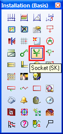
To add sockets or switching to your electrical model, you should use the default tool for electrical , which can be selected from on the toolbar. The socket tool will then be displayed on the toolbar . Click on this button to display the available socket types in the database.
Socket tool on the toolbox.
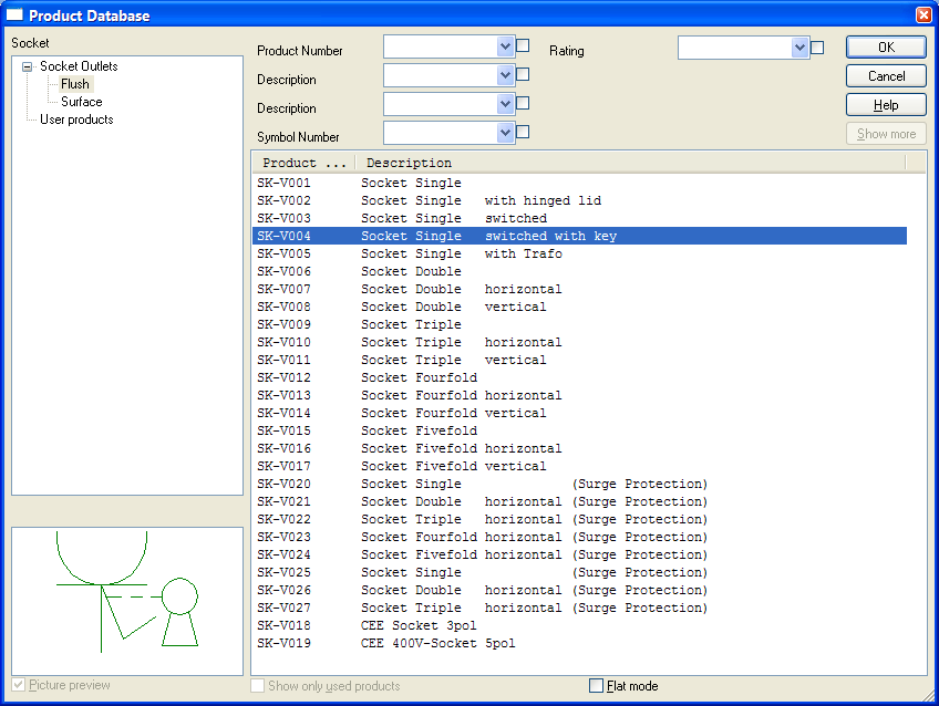
Select the type of socket you require from the selection dialog and click on Ok, the required symbol will be attached to the cursor.
For extended details on how to place the sockets and switches in the drawing, see the Chapter 7. Positioning Objects.
If you need to shift the position of the symbol on the 2D plan, for example if there is some other component such as trunking, or a light switch that would mask the socket on the drawing, you can use the 2D symbol offset feature which moves the symbol in the 2D plan but retains the location of the object in the overall model. This feature is available on the Rot/Pos/Scale tab of the socket object properties dialog.
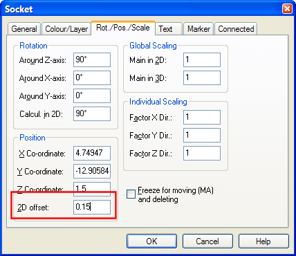
Enter the 2D symbol offset to shift the symbol to allow other components to be visible in 2D.
To add other types of components to your electrical model, you should use the default tool for electrical , which can be selected from on the toolbar. The various component tools will then be displayed on the toolbar . Click on the required button to display the available component types in the database.
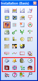
Toolbar displaying other component tools.
This is a description of the individual tools and their functions:

|
Telecoms and data components. Includes telephone and data sockets and handsets. |

|
Loudspeakers and audio devices. Includes loudspeakers, bell push switches, intercom and microphones. |

|
TV distribution components. Includes TV/FM/Satellite outlet sockets, satellite antennas, TV distribution amplifiers. |

|
Timing devices. Includes time attendance recorders, clocks and transformers. |

|
Fire and security components. Includes fire and security alarm panels, alarm sounders, access controls. |

|
Fire and smoke detectors. Includes heat detectors, smoke detectors and areas. |

|
Bus system components. EIB/KONNEX system components. |

|
Photovoltaics. Electrical solar panels. |
For extended details on how to place these objects in the drawing, see the Chapter 7. Positioning Objects.
The following video shows how to edit individual and multiple components.
[[TODO]]
< Previous Chapter - Next Section >
