There are several ways in which you can develop the lighting arrangements for your project, and you can use any or all of them in a model. Light fittings can be placed manually, for example if you are planning a simple room with a requirement for a particular light fitting type. DDS-CAD Electrical has a built–in lighting calculation module which you can use where a specific lighting level has been specified by the client. For more exacting requirements, you can use the bidirectional link with the advanced DIALux or Relux lighting design solutions.
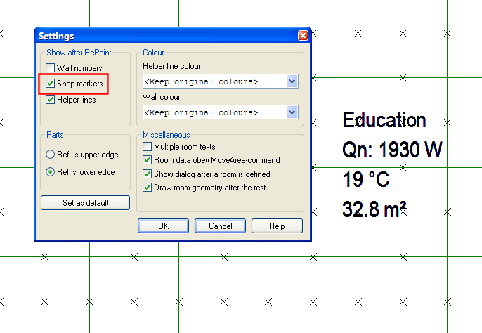
With the electrical model open, you should select the lighting tools from the available electrical applications on the toolbar. We can now begin to add some light fittings. To assist in placing the light fittings with reference to the ceiling grid, you can display all the available snap points by selecting the Tools – Options – Room Options menu item, and checking the Snap-Markers box on the Show panel in the Settings dialog. Snap markers are positioned in the centre of ceiling panels, and on the edges.
Display Snap Markers to see the snap points on the ceiling grid.
To add light fittings manually into your electrical model, you should use the default tool for electrical , which can be selected from on the toolbar. The various lighting tools will then be displayed on the toolbar . Click on the required button to display the available component types in the database.
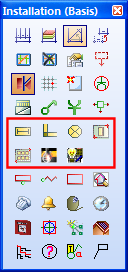
Toolbox options for lighting.
You can place fluorescent, lighting track or general GLS fittings using the first three buttons on the toolbox. Select the fitting you wish to place from the product database, and them position it in the building as required. For extended details on how to place the objects in the drawing, see the Chapter 7. Positioning Objects.
Note that the light fittings are positioned by default at the ceiling level (underside of the slab) and that if you have a suspended ceiling, or wall mounted fitting you will need to change the mounting height of the fittings.
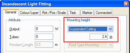
Set the mounting height for the light fittings.
If you are working with DWG or DXF floorplans directly rather than with a building model, you can lay out the light fittings using the DDS-CAD Symmetrical Objects tool, which is available on the toolbox.

Symmetrical Objects tool.
Use the "Two Points" function to describe the diagonal corners of the room, and you can then select the fittings, and desired arrangement.

Use the Two Points function to describe the room diagonal.

Choose the required number of light fittings.
It is also possible on this dialog to specify the distance to the walls for the start of the array, and also the spacing between them. The results of this array are shown below:

DDS-CAD Electrical includes a built-in light calculation based on the simple lumen method of calculation. To use this option, follow this procedure:
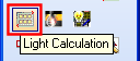
Lighting Calculation on the toolbox.
1. Click on the Light Calculation button on the toolbox to display the calculation wizard. There are three modes of operation you can use with the wizard, the first option, using an existing room, can be used where you have defined a building model. The other options can be used without a building model.
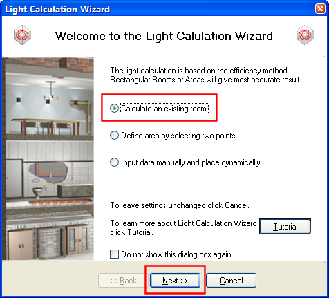
2. Select the first option, “Calculate an existing room” and press Next >>, the dialog will disappear and you should click within the room you wish to calculate. The following dialog will be displayed, showing details of the selected room:
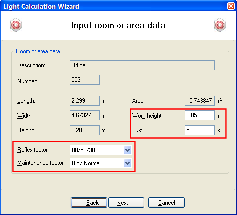
3. On this dialog you can set the working plane height and required Lux level, and then the reflection factors for ceiling/walls/floor and finally the maintenance factor. The default values for these options can be used if you are running a calculation for a standard office, which is the basis for these defaults. When you are happy with the settings, click on Next >>.
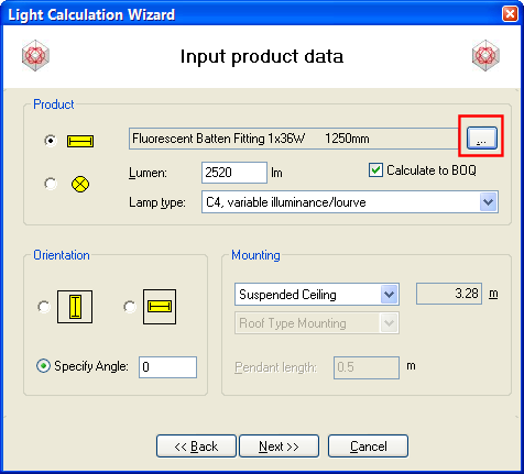
4. On this dialog you can select the type of fitting to use from the database by clicking on the […] (ellipsis) button, and also select a lamp type, and enter the lumen output to use in the calculation. You can also select the mounting height for the fittings, and set a rotation for them if required. If the fitting is a suspended fitting, you can set the length of the suspension. When you are happy with the settings, click on Next >> to start the calculation.
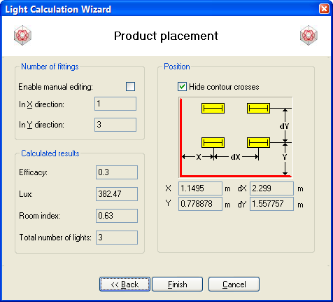
5. This dialog displays the results of the calculation and the selected arrangement of fittings. You can over-ride the results if required and enter an alternative arrangement; the program will automatically update the calculation so that you can review the changes. Check the Enable Manual Editing box to enter a new arrangement. Click on Finish and the fittings will be placed in the room.
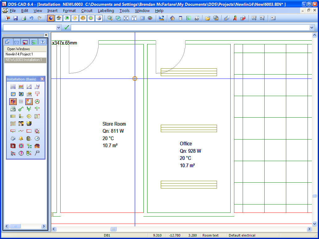
Light fittings placed in the room after the calculation has completed.
Once the calculated fitting array has been placed, you can print out the results of the calculation; double click on one of the fittings to display the Light Calculation dialog. On the Light Calculation tab, click on Print to select a report format:
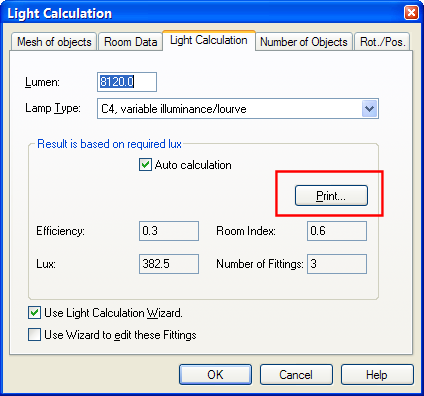
Light Calculation Tab - click on Print to view the report.
DDS-CAD reports are created using Crystal Reports. The available reports for the lighting calculation will be displayed in a File Open dialog, select one of the reports and click on Open to display the report.
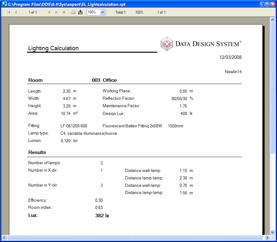
The report can be printed from this window by clicking on the Print Icon , or you can export the report to one of many available formats (Word, Excel, Text etc…) by clicking on the Export icon .
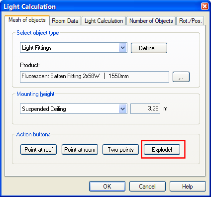
When you create a lighting calculation, the inserted fittings are grouped together to allow you to edit the calculation, if required. However, if you need to edit the fittings individually, or modify the arrangement, you can ungroup the array by double-clicking on one of the fittings to display the Light Calculation dialog. Click on Explode on the Mesh of Objects tab to ungroup the fittings. The fittings can now be edited, or moved individually.
When you require a more exacting lighting calculation than the built-in calculation in DDS-CAD, you can use the two-way interface with the state-of-the- art lighting solution Dialux or Relux tools. This facility is only available if you have created a building model. Note that this tutorial assumes you have installed, and are familiar with Dialux/Relux and does not cover the steps required to complete the calculation using this tool. You can use the interface with Dialux/Relux for a single room, or for all the rooms on a storey. To use Dialux/Relux for a single room, follow these steps (Note that this example is based on Dialux, the steps for Relux are identical):

Dialux and Relux on the toolbox.
1. With an electrical model open, and the lighting tools displayed, click on the Dialux conversion utility on the toolbar to start the process. This will display the Import/Export dialog for Dialux.

Export and Import Dialog for Dialux.
2. The Options button allows you to select the folder in which the exported STF file is saved; you may wish to use your DDS-CAD project folder, or a folder setup for use with Dialux. Click on the “Save one room to STF file” button, and then click within the boundary of a room to use this room in the export. The file will then be created.
3. Next, you need to open the STF file in Dialux; the room model will have been exported to allow you to develop your lighting layout using Dialux. When you have completed the design, export the results to the original STF file created for the export, using the File – Export – Save STF file option in Dialux.
4. To import the results of the Dialux calculation, you should click on the Open STF file button, which will display a list of the fittings used in the calculation in the Lamps imported from Dialux list.

Import data from Dialux.
5. As there is no direct mapping between the fittings used in Dialux and the DDS-CAD product database, you will need to create a mapping to place the objects in the model. Select each of the imported fittings individually, and then using the […] (ellipsis) button, create a mapping with a complimentary fitting in the product database. If there is not a direct mapping, use a similar fitting, and create a copy, then edit the details to match the imported fitting.
6. When you have completed the mapping, click on place lamps in one room to insert the array of fittings into the room. You will need to point at the room to locate the import. The fittings will then be displayed in the room.

Place the mapped fittings in the room.
You should note that the interface with Dialux does not allow you to export the lighting arrangement from DDS to Dialux, if you need to modify the arrangement and recalculate, you should re-open the project in Dialux and re-export the STF file if you require a new arrangement of fittings.

