The Electrical Schematic module can be accessed via the Drawing List on the project. To create a new schematic you should create a new drawing in the electrical module with a drawing number greater than 500. You should create a separate schematic drawing for each of the distribution boards on the project. It is possible to use the schematic module independently of the electrical installation module if required.
This chapter deals with the most commonly used functions available in the schematic module, from creating different circuit types, building models of the distribution boards, to revision handling and sheet management.
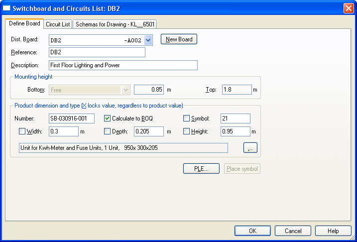
The three tabs of the circuit list dialog are as follows, and provide the principal interface to working with the schematics.

On this tab you can create and edit the configuration of the distribution boards on the project. For a more detailed explanation of the functionality of each item on this dialog, please refer to the on screen help.
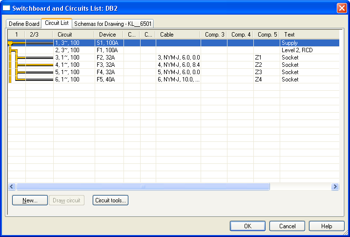
On this tab you can create, configure and edit the circuits on the distribution boards. Each row of the list represents a circuit, and there are columns available to configure the connection logic, circuit details, cable type, protective device, additional components and descriptive text. Most of these columns can be edited separately by double clicking on them, while the Level2/3 column allows the configuration of the 3rd level connection logic, and a double click will toggle between connected and unconnected.
Circuits can be edited, copied and moved using the right click context menu, and you can also update the circuit's device dimensions automatically from this menu. For a more detailed explanation of the functionality of each item on this dialog, please refer to the on screen help.
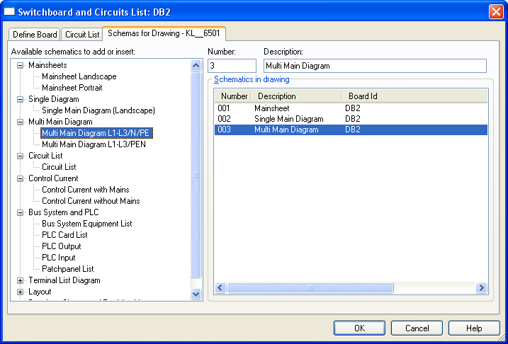
On this tab you can select the different types of schematic drawing sheets, circuit lists, board layout drawings and drawing management documentation for the board. The list on the left shows the available sheet types, while the right hand panel shows the sheet types selected for the current board. Sheet types can be added via the right click context menu, or by double clicking on the required type. Both the sheet number and description can be edited if required.
For a more detailed explanation of the functionality of each item on this dialog, please refer to the on screen help.
This video demonstrates how to navigate between the sheets using the blue arrow buttons on the toolbox, or the right click menu in the schema list. You can also see how to update the drawing sheet references, and change the resolution of the schematic drawing, which governs the number of "cells" to use on a sheet.
This short video demonstrates the available sheet types in the automation module, and how to add them to the project.
The handling of revisions on the automation module drawings is available globally, for all sheets, or locally, for individual sheets. This way, changes that affect all the drawings on the board can be identified with a global revision, for example changes to a circuit or component, while changes that only affect one or several of the sheets, such as text notes, can be identified with a revision for those sheets only. To add a revision globally, from the schemas tab, select any schematic drawing and choose Global Revision on all Sheets from the right click menu. Then you can enter the revision number/reference and a description that will be added to the drawing sheets of all the drawings of the board.
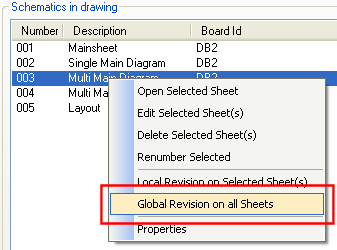
For a local revision, you need to select the specific sheet to apply the reference, then choose Local Revision on Selected Sheet(s) from the right click menu. To apply a local revision to multiple sheets at once, hold down the Ctrl key and click on each sheet reference, or the Shift key followed by the first and last sheets to select a block of sheets.
This video shows how to setup a board using various types of circuits. First a supply is defined, complete with a digital kWH meter, then a level 2 busbar is defined complete with RCD protection. Notice that when you click on the Add button to define the circuit, the program displays the available component/device objects in the database from which a selection can be made. These are pre-filtered on the load of the circuit.
The video then shows the addition of various final circuits, including lighting and bus system circuits. Note the use of the draw circuits command (see below) which is used to automatically generate the schematic drawing from the data entered in the circuit list.
The Draw Circuits command is invoked from the default toolbox in the schematic module and is used to automatically generate schematic drawings and other documentation from the database. For a new schematic drawing, select a schematic sheet type, and with the sheet displayed (you can move between sheets using the blue arrow buttons on the toolbox) select the Draw Circuits command, and then accept the default settings in the Draw Circuits dialog.
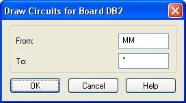
The From and To fields on this dialog allow you to select specific sections or components of the board to be generated, see the online help for more details. The default "MM" value in the From field and "*" in the To field will draw circuits starting from the first circuit in the circuit list for the initial sheet, or the next circuit for subsequent sheets, until the last circuit in the list.
Where a schematic extends beyond the current sheet, you can continue the schematic on a new sheet using the Copy Sheet as Blank command, then using the Draw Circuits command again.
This video shows how to setup the circuit list with Level 1, 2 and 3 connections. Note that to setup a level 3 connection, you need to add a new circuit to an existing final circuit by selecting the circuit number that is to be used in the Circuit Name drop down.
To create a panel arrangement drawing from your board design, you should first change the working mode to Layout Construction.
![]()
Working Mode [Layout Construction]
When you change to this Working Mode, the screen will change to allow you to layout the panel and its internal and external components. In this working mode, you have two modes of operation, for components mounted inside, and for components mounted outside the panel (on the door).
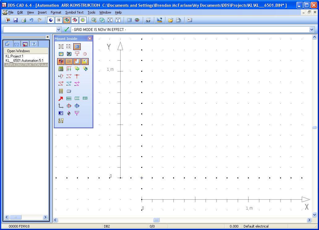
Application showing the screen for Layout Construction
To place the board model on the screen, open the Circuit List and on the Define Board tab, select Place Symbol. The board will then be attached to the cursor and can be positioned on the screen at the origin. You can then place the main modular mounting racks and boxes, snapping to the board object using the Modules for Boxes and Arrangement command on the toolbox.
Next you can start to place the individual components, by selecting the Symbol Diagram tool on the toolbox, and for each group type used on the board, select the component reference in the Ref: drop down to place each object.
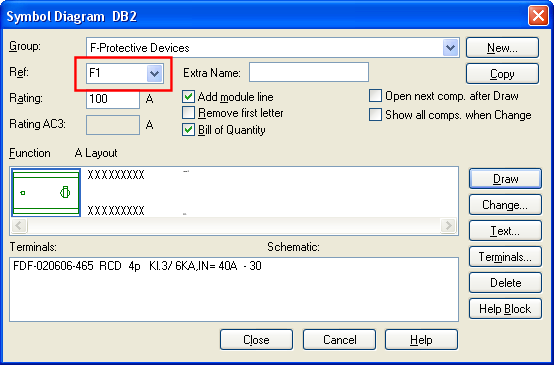
Symbol Diagram Dialog - Select each device for each type using the Ref: field
Where you have a group of protective devices to place on a row, you can use the Draw Circuits command on the toolbox to place a series of objects simultaneously. Enter the references of the first and last symbols to be placed in the appropriate fields and click on Ok; the row of symbols will be attached to the cursor and can be placed on the rack.
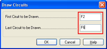
Draw Circuits - Place a series of components
To place switches, lamps etc... on the panel door, switch to the Mount in Front (Door) mode to complete the arrangement model. See the video below for further details.
To create panel arrangement drawings from the model of the panel you have created, you should start from the Layout Construction module, and execute the Generate Models command from the toolbox.

Generate Models command
This will create the various model views that can be placed on the arrangement drawings. To create an arrangement drawing, return to the default working mode for Automation and then create a sheet for the layout from the Schemas tab.
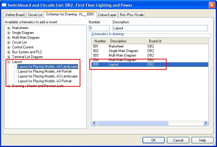
Select The Layout Arrangement Sheet Type
When you click on Ok, this new sheet will be displayed, and you can select the views to add to your arrangement drawing. Select the working mode [WM: Layout] to display the toolbox for this drawing type, and then select the views you wish to display on the drawing. The available views are: Section from Right, Section From Left, Front From Outside, Front From Inside and 3D Model. These are available on the toolbox.
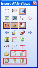
Arrangement View Tools
Once the views are placed on the drawing, you can add notes and other details as required. Follow this video for further information.
The circuit list dialog includes tools for renumbering the circuits and other devices in your project. The changes made using the renumbering tool is automatically reflected in the schematic drawings, lists, and the associated installation drawings. To update the device and circuit numbering, click on the Circuit Tools button on the circuit list.
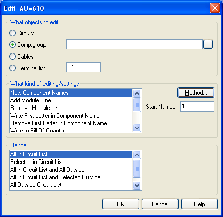
Circuit Tools Dialog
Select the object type to edit, and the method and range to apply, then click on Ok to update the circuits. For a detailed overview of the various methods available, please refer to the online help. See this video for an example of how to use this function.