In the following chapters we will cover the development of the electrical services design using DDS-CAD Electrical. Typically, the first step is to place the electrical devices in the floor plan. In AutoCAD or other basic drafting products, you might draw a light fitting with lines, but more commonly you would use blocks to represent these devices. DDS-CAD Electrical provides intelligent objects that represent real-world parts, such as wiring, fittings, devices, and panels. Understanding the different types of objects is crucial to understanding how they are displayed and how they behave when inserted into a model. Parts can have specific behaviours, such as automatic cleanup when connecting to other parts, or default insertion under certain design circumstances. The exercises in these chapters show how to add electrical devices to your project, how to modify their properties, and how to connect them together to form the electrical design for the project.
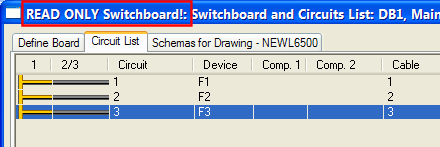
DDS-CAD has two main modules dedicated to electrical services, the Installation module, where the electrical services installation is modelled on floorplans or in a full building model, and the Schematic module, where the electrical networks can be created as schematics. Both of these modules work with a common database, so that changes in the installation are automatically reflected in the schematics, and vice versa. Consequently, if you have both the schematic and installation drawings open for a project, you will not be able to work with either schematic or installation drawings when changes have been made to the model that have not yet been saved. In this case you would see "READ ONLY Switchboard!" displayed on the circuit list window:
"READ ONLY Switchboard!" displayed on the circuit list means there have been changes made to the project in the other open module (either installation or schematic), and you should save the changes to allow you to work with the circuit list. Precious
Drawing numbers used in the Electrical installation module follow the ones used for the main building model, starting from 000 for the lowest floor level of the project. The Electrical Automation drawing numbers begin at 500 up to 999. Typically you would assign an Automation drawing number for each electrical distribution board on the project.
< Previous Chapter - Next Chapter >