 (Insert file) from the tools. Select the required file in the open dialog.
Support on this page via E-Mail...
This may be one of the most important chapters. It is quite common to receive architectural files as DWG, and when you have read this you will be able to get DWG files, scale, rotate and upgrade the architectural basis.
First, save the received DWG file on the disk. We recommend to save it in the folder for the current project.
To find the current project folder, select from the menu ”Tools - > Open active project with the Windows Explorer”
The following points must be correct before starting the project.
Open the drawing in the project in which you are to import the received dwg file. Select (Insert file) from the tools. Select the required file in the open dialog.
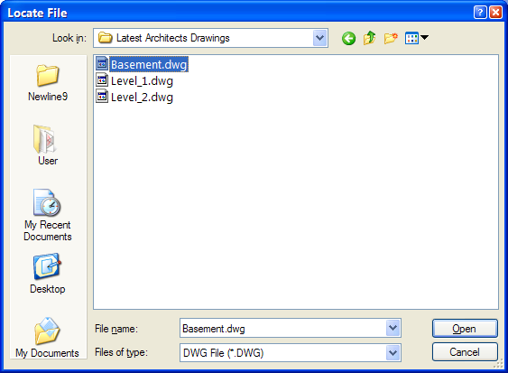
Press [Open] and select [OK] in the \Insert file dialog.
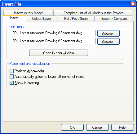
Convert the selected dwg file to cfi file with the same name and position in the drawing.
To check that the scaling is correct, zoom in on a known target in the drawing, for instance a door – usually about 1 meter wide.
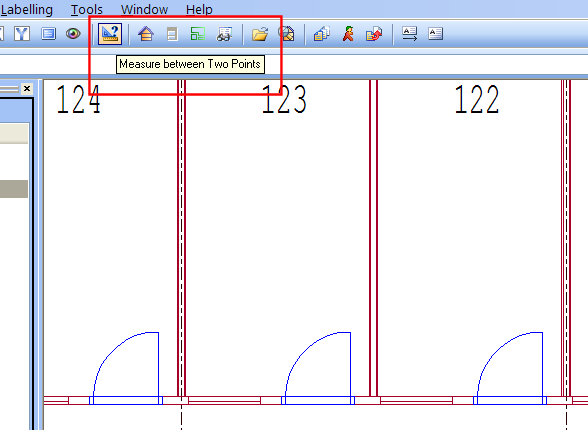
Select  (Measure between two points) in the tools. Point and click the left mouse button i each end of the door.
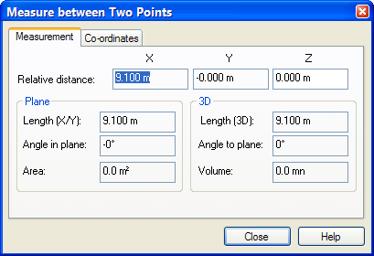
The measured distance is displayed in meter in the dialog above.
Here the length is 9.100 meters. The drawing is thereby incorrectly scaled 10 times too large, and must be scaled down.
To edit the scaling, double-click on a line in the imported file. In the open dialog box you select the flag Positioning/Scaling:
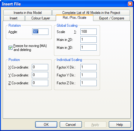
Edit the value in the field Scaling so that the measured value corresponds with reality. Confirm the dialog with [OK] , select  (Repaint screen) on the toolbar and zoom up the drawing again. Measure once again on the same spot as last time. If the measure is correct you can continue – if not, you will have to repeat changing the scale until it is correct.
If the architectural basis is rotated in an angle difficult to work with, you can rotate it to fit your setup. Check that the DWG file position is 0 in the X, Y and Z position. Measure first how much you want to rotate the DWG file, the double-click on a line in the drawing, and select the flag Position/Scale/Rotate.
If the building has got several storeys, it might be an advantage to set the origin of the architectural drawings on each storey. This will position the storeys exactly on top of each other when you are to lead risers through storeys. Find a point on the architectural drawing with exactly the same position in all storeys. Such a point could be an axis, the corner of a lift shaft, the corner of a chimney, or the external corner of a wall. When you have found such a reference point, double-click on a line in the DWG drawing as the properties dialog shows. Press the button ”Open file for editing”. A separate window with the DWG file is opened, and you can set the origin with the button ”Indicate new origin”. When a new origin has been indicated, close the DWG drawing and save the changes.
To get the correct risers for pipes and ducts through the stories, the storey height must be entered correctly for all storeys. Pipes under ground will only get a small piece of pipe above ground floor level. Therefore, enter the storey height for the pipes under ground to 0.1 meter. The storey height for the other storeys is entered like the real storey height. See chapter 6 – Room database for further information about storey height.
You will find the storey height by means of the button ”Room survey” on the toolbar on top of screen.
An architectural basis often consists of several storeys drawn together.
3.14 "Model file" is a CAD file containing a editable CAD drawing in the scale 1:1
8.10 Transfer of model files
If nothing else is indicated, a model file should not hold more than one storey. The storey plans should have the same origin.
In this case you must split the architectural base and create a separate drawing for each storey.
To do this, close the project and open a DWG file from the menu (File -> Open DXF/DWG). Select the button ”File properties”. Tick off for ”Explode INSERTS (single objects)”
Select all, except the one storey. Set Origin and save with a new file name. Repeat this until every storey has got individual drawings.
In most projects revised architect files will appear which you must keep upgraded. You are recommended to create separate folders with an upgrade date under the project folder and save the new files here.
When having saved the revised files, you can replace the existing ghost file with the new one. Double-click on a line in the ghost file, press the button ”Browse” in the field 2D file and find the new architectural file. Set origin and continue.
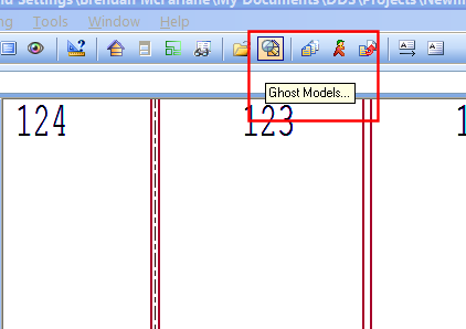
When all storeys are imported into your project, you should compare all storeys to check if they are positioned right on top of each other. The function for comparing project drawings is found on the toolbar
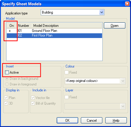
In Compare Project drawings, all models in your project are listed. They must be saved before being displayed in this list. Click on the model you want to see, and then click "Display selected drawing". You can have different colours on each floor to separate them.
See video how the comparison turns out if you have NOT been careful with the points above
See video how the comparison turns out if you HAVE been careful with the points above
Tip: If you work multidisciplinary, i.e. with both sanitary, ventilation and/or electrical, the most effective manner is to import the DWG floorplans into the application Building/Plan drawing, and then compare ("ghost") the plan drawings in the respective technical applications. You will then only have to upgrade the revised architectural files once, and then be up-to-date in the other applications.
See video how to create a Plan drawing and get the DWG basis.
See video how to "ghost" a Plan drawing into Sanitary, Ventilation and Electrical
< Previous Chapter - Next Chapter >
