We describe possible strategies to build, edit and develop a network in a step-wise fashion in a building with several storeys. You can deploy the operations for pipe networks with various media.
For the described actions, open a model of the discipline.
Zur allgemeinen Strategie
To make the job effective, consider the space requirements of the system from the beginning. Work with the expected dimensions, and think about insulation as well as possible size changes using a network calculation.
| Prepare and transfer risers. |
|
| |
|
| On the storeys: design and gradually refine the network structure with the help of load objects |
|
| |
|
| Remove the load object, connect objects with a dedicated purpose. |
|
|
|
| Prepare and transfer risers. |
|
| |
| |
|
| On the storeys: design and gradually refine the network structure with the help of load objects |
|
| |
|
| Remove the load object, connect objects with a dedicated purpose. |
|
|
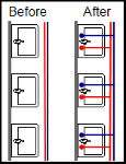
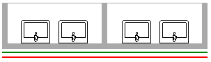
Prepare and transfer risers.
| Main lines and positions of the risers |
|
| |
|
| First riser with a load object |
|
| |
|
| Prepare risers for the entire storey |
|
| |
|
| Transfer continuous risers to all storeys |
|
| |
|
| Finish risers |
|
|
|
| Main lines and positions of the risers |
|
| |
| |
|
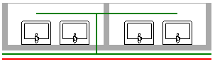
| First riser with a load object |
|
| |
|
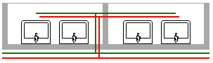
| Prepare risers for the entire storey |
|
| |
|
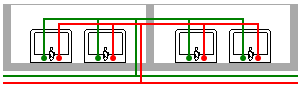
| Transfer continuous risers to all storeys |
|
| |
|
| Finish risers |
|
|
|
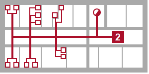
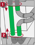
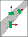
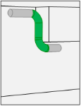
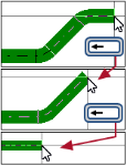
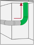
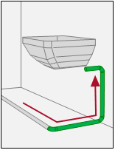
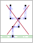
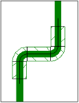
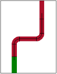
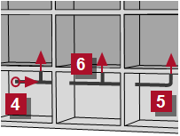
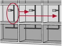
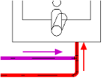
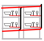
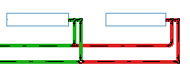
If the origin point of the network  is known, start there with the pipework, move to the furthest rising point is known, start there with the pipework, move to the furthest rising point  and end at the transfer to the next storey. Further risers and end at the transfer to the next storey. Further risers  can branch and also be transferred from there. can branch and also be transferred from there.
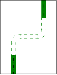
If you only know the riser point, first define only the vertical risers. In this case, move the network together at a later point. The order is irrelevant
See also
|
|
| Main lines and positions of the risers |
|
| |
|
| First riser with a load object |
|
| |
| |
|
| Prepare risers for the entire storey |
|
| |
|
| Transfer continuous risers to all storeys |
|
| |
|
| Finish risers |
|
|
|
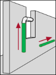
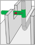
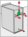
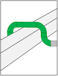
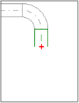
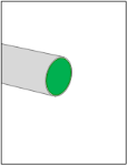
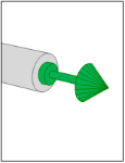
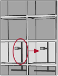
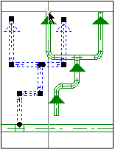
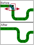
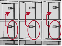
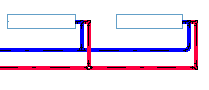
Open the next floor and take the first riser  . Connect the load object . Connect the load object  into the riser. into the riser.
See also
|
|
| Main lines and positions of the risers |
|
| |
|
| First riser with a load object |
|
| |
|
| Prepare risers for the entire storey |
|
| |
| |
|
| Transfer continuous risers to all storeys |
|
| |
|
| Finish risers |
|
|
|
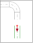
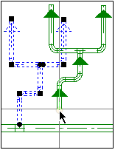
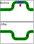
If you need further risers on this storey with the same medium and same dimension, copy the first riser using “Copy and Paste”.
See also
|
|
| Main lines and positions of the risers |
|
| |
|
| First riser with a load object |
|
| |
|
| Prepare risers for the entire storey |
|
| |
|
| Transfer continuous risers to all storeys |
|
| |
| |
|
| Finish risers |
|
|
|
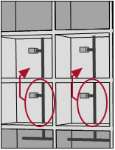
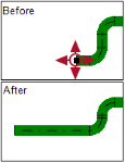
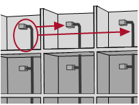
The prepared risers of one storey can also be transferred to all storeys using “Copy and Paste”. Under the most favourable conditions, you only need one step for each storey.
See also
|
|
| Main lines and positions of the risers |
|
| |
|
| First riser with a load object |
|
| |
|
| Prepare risers for the entire storey |
|
| |
|
| Transfer continuous risers to all storeys |
|
| |
|
| Finish risers |
|
| |
|
|
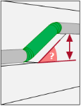
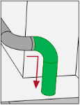
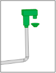
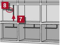
Work manually with the end of the first riser (e.g. in the top floor). Then you can also transfer this construction to all the other risers using “Copy and Paste”.
|
|
|
| Prepare and transfer risers. |
|
| |
|
| On the storeys: design and gradually refine the network structure with the help of load objects |
|
| |
| |
|
| Remove the load object, connect objects with a dedicated purpose. |
|
|
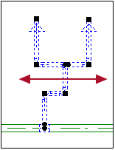
On the storeys: design and gradually refine the network structure with the help of load objects
While advancing in the design process, you can refine the network construction on the storeys. You split the bigger load objects into smaller units with more accurate values and calculate the system again and again.
|
| Prepare and transfer risers. |
|
| |
|
| On the storeys: design and gradually refine the network structure with the help of load objects |
|
| |
|
| Remove the load object, connect objects with a dedicated purpose. |
|
| |
|
Remove the load object, connect objects with a dedicated purpose.
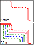
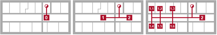
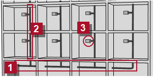
Systematic process when connecting objects
|
Step 1
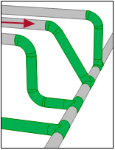
You draw the main lines manually. If multiple pipes of different mediums run parallel to each other, you can make DDScad generate them automatically.
|
|
Step 2
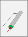
Also the distribution pipes of each medium are prepared manually.
|
|
Step 3
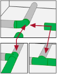
A single distribution pipe segment can be copied and connected to the main system.
|
|
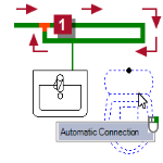
Step 4
Finally, connect the objects using the automatic connection function.
|
|
Special items in various networks
Specific characteristics must be considered for correct composition for the network with various media.
| Potable water |
|
| |
|
| Heating |
|
| |
|
| Waste water |
|
|
|
| Potable water |
|
| |
| |
|
| Heating |
|
| |
|
| Waste water |
|
|
Don’t forget the insulation!
The piping of the media PWH Hotwater and PWH-C Circulation must be completely insulated!
DDScad checks the temperature of the PWH Hotwater medium and the environmental temperature which is predominant in the space. The insulation used determines the resulting temperature loss and affects the size of the pump. The rule is: the better the insulation, the smaller the circulation pump.
The insulation materials used are shown in the parts list and are displayed in the model using their thickness. This allows you to visualize the space needs for pipework.
No bypasses
The system cannot be calculated if there is a bypass in the pipe network.
Correctly connect the circulation
|
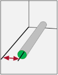
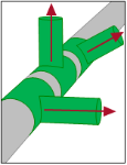
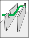
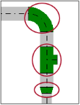
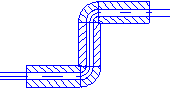
Move the PWH-C Circulation medium in such a way that the end meets a hot water line. The connection must be done in such a way that the PWH Hotwater medium flows through the tee with no change in direction.
|
Correctly build the ring network
|
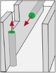
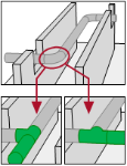
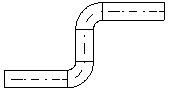
Construct the ring as a loop, which is created by connecting it via a tee  . In the properties of the tee, activate . In the properties of the tee, activate  Ring line tee Ring line tee
The draw-off points are connected via a flow-through wall plate. Use function for this purpose.
|
|
| Potable water |
|
| |
|
| Heating |
|
| |
| |
|
| Waste water |
|
|
Don’t forget the insulation!
The insulation materials used are shown in the parts list and are displayed in the model using their thickness. This allows you to visualize the space needs for pipework.
No bypasses
The system cannot be calculated if there is a bypass in the pipe network.
You divide a pipe network with several pumps into subsystems.
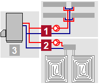
|
Each string with its own pump is considered a subsystem. You separate it from the whole system by an object of type 'Hydraulic switch' ().
Note the following situations:
Parallel heating/cooling circuit with pump
For sub-systems which work with the system temperatures of the heat/cold generator.
 Mixing circuit Mixing circuit
For sub-systems which work with the system temperatures of the heat/cold generator.
All elements between the heat generator or chiller up to the hydraulic switch of the respective subsystem are considered as the primary circuit  . Here you can define the calculation point for the entire system. . Here you can define the calculation point for the entire system.
Important!
No direct connection of consumers to the primary circuit .
|
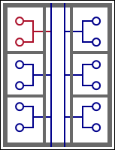
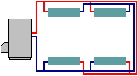
Correctly compose the pipe network for the “Tichelmann” system
|
DDScad provides calculation of heating pipe networks which are designed in adherence to the “Tichelmann” system. Make sure that the supply and return are approximately the same length.
|
|
| Potable water |
|
| |
|
| Heating |
|
| |
|
| Waste water |
|
| |
|
|
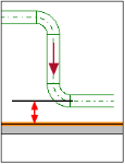
Always consider the slope from the start when constructing a waster water system. The setting is a prerequisite for the automatic connection of objects and pipe system calculation.
|
|
Design pipework
| Pipework Start |
| |
| Pipework Course |
| |
| Pipework Terminate |
|
|
| |
|
| |
|
| Navigate in the pipe network |
|
| |
|
| Insert fitting |
|
| |
|
| Auxiliary functions and operations |
|
|
|
| Pipework Start |
| |
| Pipework Course |
| |
| Pipework Terminate |
|
|
| |
| |
| |
| |
| |
| |
| |
| |
| |
|
| |
|
| Navigate in the pipe network |
|
| |
|
| Insert fitting |
|
| |
|
| Auxiliary functions and operations |
|
|
Pipework Start
Variants for starting a pipeline in different situations.
|
| Pipework Start |
| |
| Pipework Course |
| |
| Pipework Terminate |
|
|
| |
| |
| |
| |
| |
| |
| |
| |
| |
|
| |
|
| Navigate in the pipe network |
|
| |
|
| Insert fitting |
|
| |
|
| Auxiliary functions and operations |
|
|
Pipework Course
Operations to construct the route of the active pipework.
 [D] / [D] /
[Ctrl]+[D]
[PgUp]/ [Home]
[PgDn]/ [End]
[Shift]+[PgUp] / [Home]
[Shift]+[PgDn] / [End]
[Backspace]
|
| Pipework Start |
| |
| Pipework Course |
| |
| Pipework Terminate |
|
|
| |
| |
| |
| |
| |
| |
| |
| |
| |
|
| |
|
| Navigate in the pipe network |
|
| |
|
| Insert fitting |
|
| |
|
| Auxiliary functions and operations |
|
|
Pipework Terminate
Operations to finish the active pipe.
[ESC]
[Enter]
[Ctrl]+[End]
[Ctrl]+[Home]
|
| Pipework Start |
| |
| Pipework Course |
| |
| Pipework Terminate |
|
|
| |
| |
| |
| |
| |
| |
| |
| |
| |
|
| |
|
| Navigate in the pipe network |
|
| |
| |
|
| Insert fitting |
|
| |
|
| Auxiliary functions and operations |
|
|
Navigate in the pipe network
|
| Pipework Start |
| |
| Pipework Course |
| |
| Pipework Terminate |
|
|
| |
| |
| |
| |
| |
| |
| |
| |
| |
|
| |
|
| Navigate in the pipe network |
|
| |
| |
|
| Insert fitting |
|
| |
| |
|
| Auxiliary functions and operations |
|
|
Insert fitting
Fittings and components are always inserted into an existing pipe system afterwards. Select the desired description.
|
| Pipework Start |
| |
| Pipework Course |
| |
| Pipework Terminate |
|
|
| |
| |
| |
| |
| |
| |
| |
| |
| |
|
| |
|
| Navigate in the pipe network |
|
| |
| |
|
| Insert fitting |
|
| |
| |
|
| Auxiliary functions and operations |
|
| |
|
Auxiliary functions and operations
Various help functions support the construction of a pipe system. Take advantage of these functions when required.
|
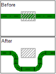
Edit pipe system
Important!
If you shift a riser, then check the risers on the neighbouring storeys. The connected risers for all floors must stand superimposed over one another on all storeys after the operation is completed.
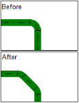
| General editing functions |
|
| |
|
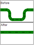
| Edit course |
|
| |
|
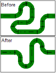
| Change properties in the course |
|
|
|
| General editing functions |
|
| |
| |
|
| Edit course |
|
| |
|
| Change properties in the course |
|
|
|
| General editing functions |
|
| |
|
| Edit course |
|
| |
| |
|
| Change properties in the course |
|
|
|
| General editing functions |
|
| |
|
| Edit course |
|
| |
|
| Change properties in the course |
|
| |
|
|
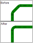
Configure presentation
Use the options in the menu for situation-appropriate presentation of the pipe network.
|
|
| |
|
|
| On 
|
|
Colors show the status of a part of the system in regards to all defined limit values.
| |
The line is not calculated or the limit value is exceeded. |
| |
The limit value was retained. |
|
| Off |
|
Colors show the medium. |
|
|
|
| |
|
|
| On
|
|
Colors show the medium in the rendered model.
| |
The pipework shows in the rendered model in accordance with the materials used. |
| |
The limit value was retained. |
|
| Off |
|
Colors show the medium. |
|
 . Enter the estimated or roughly calculated demand value in these objects.