We describe possible strategies to build, edit and develop a network in a step-wise fashion in a building with several storeys.
For the described actions, open a model of the discipline.
Zur allgemeinen Strategie
To make the job effective, consider the space requirements of the system from the beginning. Work with the expected dimensions, and think about insulation as well as possible size changes using a network calculation.
| Working in the riser shaft |
|
| |
|
| On the storeys: design and gradually refine the network structure with the help of load objects |
|
| |
|
| Remove the load object, connect objects with a dedicated purpose. |
|
|
|
| Working in the riser shaft |
|
| |
| |
|
| On the storeys: design and gradually refine the network structure with the help of load objects |
|
| |
|
| Remove the load object, connect objects with a dedicated purpose. |
|
|
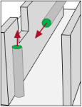
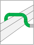
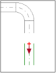
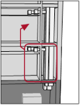
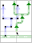
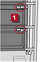
Working in the riser shaft
|
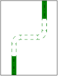
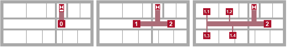
The positions of the ventilation centre and manhole are set with the complete building design. You know how to measure the total air volumes and can measure the cross section of the main channels with this.
You develop the network in a step-wise fashion using these assumptions. Simulate the consumer in this early stage using load objects in order to calculate the network in each processing step  . Enter the estimated or roughly calculated demand value in these objects. . Enter the estimated or roughly calculated demand value in these objects.
|
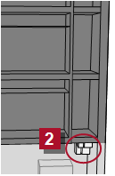
| Prepare the positions in the riser shaft |
|
| |
|
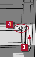
| Take to the first storey, use a load object |
|
| |
|
| Transfer to the following storeys |
|
|
|
| Prepare the positions in the riser shaft |
|
| |
| |
|
| Take to the first storey, use a load object |
|
| |
|
| Transfer to the following storeys |
|
|
|
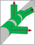
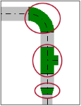
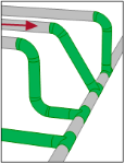
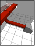
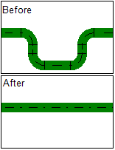
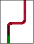
Start a ventilation duct for each medium starting with the ventilation central equipment room, lead it to a shaft and transfer it to the next storey  . .
See also
|
|
| Prepare the positions in the riser shaft |
|
| |
|
| Take to the first storey, use a load object |
|
| |
| |
|
| Transfer to the following storeys |
|
|
|
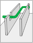
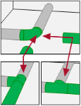
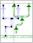
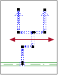
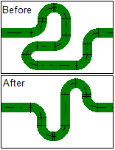
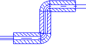
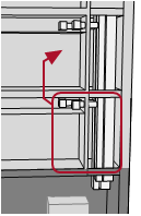
Open the next storey and take all  media into the continuous ventilation duct. Produce a branch and end it with a load object media into the continuous ventilation duct. Produce a branch and end it with a load object  in order to prepare the distribution on the storey. in order to prepare the distribution on the storey.
See also
|
|
| Prepare the positions in the riser shaft |
|
| |
|
| Take to the first storey, use a load object |
|
| |
|
| Transfer to the following storeys |
|
| |
|
|
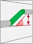
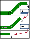
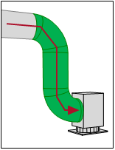
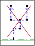
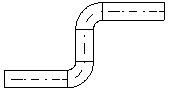
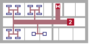
You can transfer the prepared ventilation ducts of one storey to all floors using Copy and Paste. You also take over the connected load objects and correct their discharge units to the conditions of the respective storeys.
See also
|
|
| Prepare the positions in the riser shaft |
|
| |
|
| Take to the first storey, use a load object |
|
| |
|
| Transfer to the following storeys |
|
| |
|
| |
|
| |
|
| |
|
| |
|
|
|
| Working in the riser shaft |
|
| |
|
| On the storeys: design and gradually refine the network structure with the help of load objects |
|
| |
| |
|
| Remove the load object, connect objects with a dedicated purpose. |
|
|
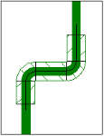
Refine the network construction
While advancing in the design process, you can refine the network construction on the storeys. You split the bigger load objects into smaller units with more accurate values and calculate the system again and again.
|
| Working in the riser shaft |
|
| |
|
| On the storeys: design and gradually refine the network structure with the help of load objects |
|
| |
|
| Remove the load object, connect objects with a dedicated purpose. |
|
| |
|
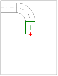
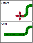
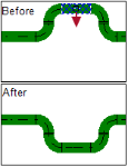
Remove the load object, connect objects with a dedicated purpose.
|
If the positions of the objects with a dedicated purpose (Air TerminalPlenum) are clear, remove the load objects and attach the appropriated objects to the duct network. (Air TerminalPlenum) are clear, remove the load objects and attach the appropriated objects to the duct network.
|
|
Design ventilation duct
| Ventilation duct Start |
| |
| Ventilation duct Course |
| |
| Ventilation duct Terminate |
|
|
| |
|
| |
|
| Insert object in duct |
|
| |
|
| Auxiliary functions and operations |
|
|
|
| Ventilation duct Start |
| |
| Ventilation duct Course |
| |
| Ventilation duct Terminate |
|
|
| |
| |
| |
| |
| |
| |
| |
| |
| |
|
| |
|
| Insert object in duct |
|
| |
|
| Auxiliary functions and operations |
|
|
Ventilation duct Start
Variants for starting a ventilation duct in different situations.
|
| Ventilation duct Start |
| |
| Ventilation duct Course |
| |
| Ventilation duct Terminate |
|
|
| |
| |
| |
| |
| |
| |
| |
| |
| |
|
| |
|
| Insert object in duct |
|
| |
|
| Auxiliary functions and operations |
|
|
Ventilation duct Course
Operations to construct the route of the active ventilation duct.
 [PgUp]/ [Home]
[PgDn]/ [End]
[Shift]+[PgUp] / [Home]
[Shift]+[PgDn] / [End]
[Backspace]
|
| Ventilation duct Start |
| |
| Ventilation duct Course |
| |
| Ventilation duct Terminate |
|
|
| |
| |
| |
| |
| |
| |
| |
| |
| |
|
| |
|
| Insert object in duct |
|
| |
|
| Auxiliary functions and operations |
|
|
Ventilation duct Terminate
Operations to finish the active ventilation duct.
[ESC]
[Enter]
[Ctrl]+[End]
[Ctrl]+[Home]
|
| Ventilation duct Start |
| |
| Ventilation duct Course |
| |
| Ventilation duct Terminate |
|
|
| |
| |
| |
| |
| |
| |
| |
| |
| |
|
| |
|
| Insert object in duct |
|
| |
| |
|
| Auxiliary functions and operations |
|
|
Insert fitting
These objects are always inserted into an existing pipe system afterwards.
Select the desired description.
|
| Ventilation duct Start |
| |
| Ventilation duct Course |
| |
| Ventilation duct Terminate |
|
|
| |
| |
| |
| |
| |
| |
| |
| |
| |
|
| |
|
| |
|
| Insert object in duct |
|
| |
| |
|
| Auxiliary functions and operations |
|
| |
|
Auxiliary functions and operations
Various help functions support the construction of a pipe network. Take advantage of these functions when required.
|
Edit ventilation system
Important!
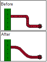
If you shift a riser, then check the risers on the neighbouring storeys. The connected risers for all floors must stand superimposed over one another on all storeys after the operation is completed.
| General editing functions |
|
| |
|
| Edit course |
|
| |
|
| Change properties in the course |
|
|
|
| General editing functions |
|
| |
| |
|
| Edit course |
|
| |
|
| Change properties in the course |
|
|
|
| General editing functions |
|
| |
|
| Edit course |
|
| |
| |
|
| Change properties in the course |
|
|
|
| General editing functions |
|
| |
|
| Edit course |
|
| |
|
| Change properties in the course |
|
| |
|
Partially convert into a flexible conduit
|
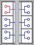
Configure presentation
Use the options in the menu for situation-appropriate presentation of the pipe network.
|
|
| |
|
|
| On 
|

|
Colors show the status of a part of the system in regards to all defined limit values.
| |
The lines are not calculated or have no volume flow rate. |
| |
The speed is within tolerances. |
| |
|
|
The speed is too low. Color saturation shows the degree of tolerance deviation. |
| |
The speed is too high. |
|
| Off |

|
Colors show the medium. |
|
|
|
| |
|
|
| On
|
|
Colors show the medium in the rendered model.
| |
The network shows in the rendered model in accordance with the materials used. |
| |
The speed is within tolerances. |
| |
|
|
The speed is too low. Color saturation shows the degree of tolerance deviation. |
| |
The speed is too high. |
|
| Off |
|
Colors show the medium. |
|